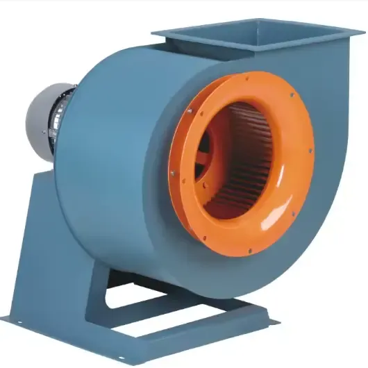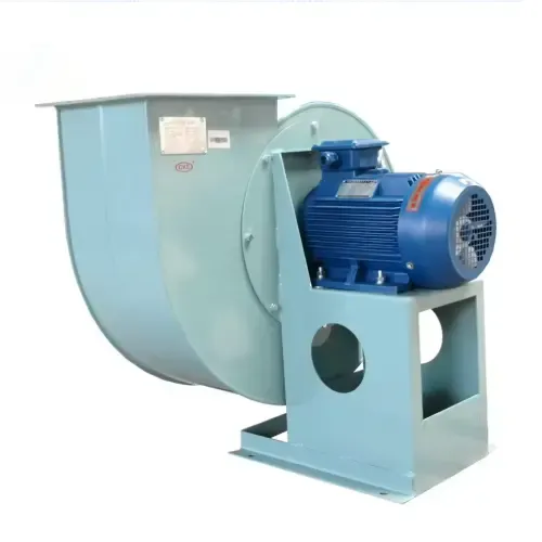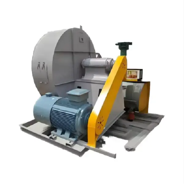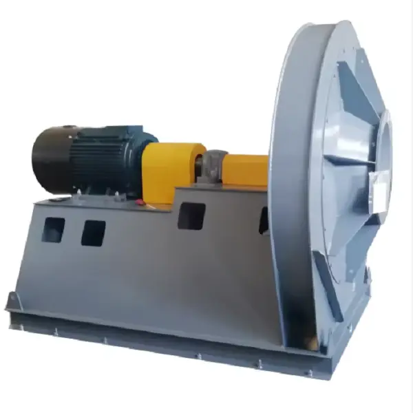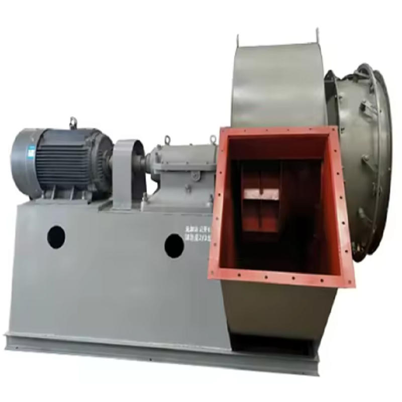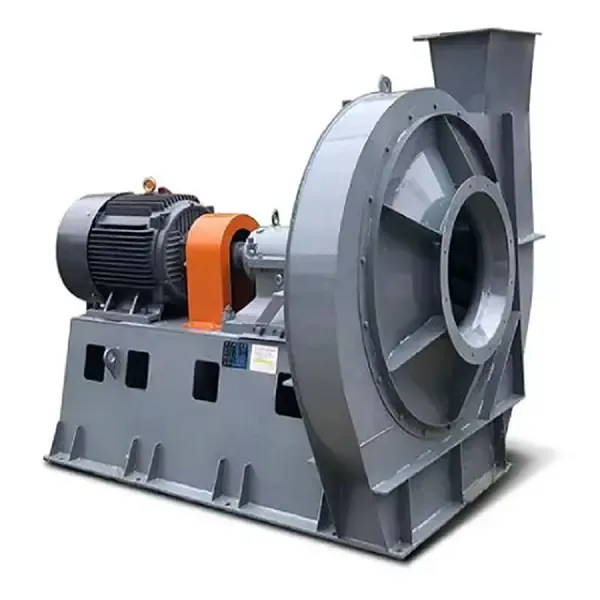
In many industrial boiler plants, the induced draft fan is one of the largest continuous electrical loads in the flue gas system. High-Efficiency Boiler Induced Draft Fans can reduce this load, but simply installing a larger or newer fan does not guarantee lower energy consumption. The real savings come from matching the fan to the actual airflow, system pressure, flue gas temperature, and boiler load.
A common problem is that an ID fan is selected according to boiler capacity alone. In actual operation, however, the required duty changes with fuel type, excess air, flue gas temperature, dust collector resistance, duct configuration, and boiler load. High-Efficiency Boiler Induced Draft Fans should therefore be selected from the complete system operating conditions rather than from motor power or fan size alone.
Before selecting High-Efficiency Boiler Induced Draft Fans, determine whether the specified airflow is given at normal conditions or at the actual fan inlet condition.
Flue gas expands significantly as temperature increases. For a simple calculation:
Q₂ = Q₁ × T₂ / T₁
where Q is volumetric flow and T is absolute temperature in Kelvin.
For example, if the required flue gas flow is 30,000 Nm³/h at 20°C and the gas temperature at the fan inlet is 180°C:
Q₂ = 30,000 × 453 / 293 ≈ 46,350 m³/h
This means the fan actually handles approximately 46,350 m³/h at the stated temperature, assuming the pressure correction is small for this preliminary calculation.
Using the standard-condition flow directly for fan selection could therefore result in an undersized machine. High-Efficiency Boiler Induced Draft Fans need to be selected using clearly defined gas conditions so that the operating point on the fan curve is correct.
Fan efficiency cannot compensate for an incorrectly designed flue gas system.
For High-Efficiency Boiler Induced Draft Fans, the required pressure should include all major resistance points:
Boiler gas passages
Economizer
Air preheater
Cyclone
Bag filter or ESP
Scrubber
Ductwork
Elbows and transitions
Dampers
Chimney
Expansion joints and other components
A practical calculation might look like this:ComponentPressure LossBoiler and heat-transfer section850 PaDuctwork450 PaBag filter1,200 PaDamper and transitions250 PaChimney and outlet350 PaTotal3,100 PaIf the system resistance is underestimated, the fan will not reach the required airflow. If it is significantly overestimated, the fan may operate at an unnecessarily high pressure and consume more power.
This is one reason High-Efficiency Boiler Induced Draft Fans should always be selected together with a system resistance calculation.
One of the easiest problems to find during a plant inspection is a fan running at nearly full speed while its inlet or outlet damper is heavily throttled.
The fan continues to generate pressure, while the damper creates additional resistance to reduce airflow. The energy used to overcome this artificial resistance is largely wasted.
For High-Efficiency Boiler Induced Draft Fans, variable-speed control is often more effective when the boiler has a wide operating range.
Fan affinity laws provide a useful first estimate:
Q₂ / Q₁ = N₂ / N₁
P₂ / P₁ ≈ (N₂ / N₁)³
For example, if fan speed is reduced from 100% to 80%:
P₂ / P₁ ≈ 0.8³ = 0.512
The theoretical fan power becomes approximately 51% of the original value under comparable operating conditions.
Actual plant savings will depend on the system curve, motor efficiency, VFD efficiency, and the new operating point. Still, the cubic relationship explains why speed control can be much more effective than throttling.
Installing a VFD is not enough by itself.
A poorly configured VFD can still waste energy if the fan runs faster than necessary. The control system should respond to the actual furnace draft requirement.
A typical arrangement is:
Furnace pressure sensor → PID controller → VFD → ID fan motor
For example, if the required furnace pressure is -50 Pa and the measured pressure is -80 Pa, the control system should gradually reduce fan speed instead of allowing the fan to continue operating at full speed.
The target pressure must be established according to the boiler manufacturer's combustion requirements. Excessive negative pressure is not automatically better.
With properly configured High-Efficiency Boiler Induced Draft Fans, the objective is to maintain stable furnace pressure while moving only the amount of flue gas required by the current boiler load.
Impeller condition has a direct effect on fan performance.
In biomass, coal, waste-fired, and other dusty boiler applications, ash can accumulate on the blades. If the deposit is uneven, it changes the mass distribution of the rotating assembly and can cause vibration.
A simple maintenance inspection should include:
Lock out the fan and follow the plant's isolation procedure.
Inspect the impeller through the access opening.
Check for ash buildup on both sides of the blades.
Inspect leading edges for erosion.
Check for cracks or deformation.
Rotate the assembly manually when safe to do so.
Check bearing condition and shaft alignment after cleaning.
A fan that originally operated smoothly but develops increasing vibration over several months should not immediately be blamed on the motor.
For High-Efficiency Boiler Induced Draft Fans, maintaining the aerodynamic shape and mass balance of the impeller is essential to retaining the designed performance.
Temperature affects both gas density and mechanical design.
When flue gas temperature increases, its density decreases. The actual volumetric flow therefore increases for the same mass flow.
High temperature can also affect:
Shaft expansion
Bearing temperature
Lubricant life
Coupling alignment
Casing expansion
Sealing
Motor cooling
Fan material selection
For High-Efficiency Boiler Induced Draft Fans, the maximum continuous gas temperature should be specified before finalizing the fan construction.
For applications with significant temperature variation, thermal expansion should be considered during installation. Cold alignment that looks correct during shutdown may change after the equipment reaches operating temperature.
A dirty bag filter is often mistaken for an undersized fan.
Suppose an industrial boiler originally operates with a bag-filter pressure drop of 900 Pa. After months of operation, the pressure drop rises to 1,500 Pa because of dust loading or poor cleaning performance.
The fan now has to overcome an additional:
1,500 - 900 = 600 Pa
If the fan speed is increased to compensate, motor power can rise significantly.
Before increasing the speed of High-Efficiency Boiler Induced Draft Fans, technicians should measure pressure before and after the dust collector.
If the pressure drop has increased abnormally, inspect:
Filter bags
Pulse-jet cleaning
Dust discharge system
Hopper blockage
Air leakage
Differential-pressure sensor
Fixing the high-resistance component can be more economical than modifying the fan.
Consider a biomass boiler operating with:
Steam capacity: approximately 12 t/h
Flue gas flow at operating condition: approximately 42,000 m³/h
Fan inlet temperature: 165°C
Required fan pressure: approximately 2,800 Pa
Motor power: 75 kW
Fan speed: approximately 1,480 rpm
Existing control: inlet damper
Typical boiler load: 60–90%
During normal production, operators noticed that the ID fan motor current remained relatively high even when boiler output dropped.
The first inspection found no serious bearing problem, and the impeller was structurally acceptable.
The next step was to compare fan speed, damper position, furnace pressure, and boiler load.
At approximately 65% boiler load, the fan was still operating close to full speed while the inlet damper was significantly closed. The system was therefore controlling airflow mainly through throttling.
The solution was to install a VFD and change the control logic so that fan speed responded to furnace pressure and boiler load.
After commissioning, the fan no longer needed to operate near maximum speed during low-load periods. The exact energy saving depends on the final operating point and plant production schedule, but the modification reduced unnecessary fan operation and provided more stable draft control.
This case illustrates an important point: High-Efficiency Boiler Induced Draft Fans are not only about fan hardware. Control strategy can have just as much influence on energy consumption.
Motor current is useful, but it should be treated as one operating parameter rather than a complete diagnosis.
For High-Efficiency Boiler Induced Draft Fans, operators should trend:
Motor current
Motor power
Fan speed
Furnace pressure
Fan inlet pressure
Fan outlet pressure
Flue gas temperature
Vibration
Bearing temperature
Filter differential pressure
For example, if motor current increases while airflow remains unchanged, investigate whether system resistance has increased.
If current and vibration increase together, inspect the impeller, bearings, coupling, and alignment.
If current decreases while furnace pressure becomes insufficient, check whether the fan speed, damper position, duct leakage, or impeller condition has changed.
Trend data is much more useful than a single reading taken during a maintenance visit.
Oversizing is another common source of inefficient operation.
A fan selected with excessive airflow and pressure may spend most of its operating time away from the intended design point. Operators then compensate by closing dampers or reducing speed.
When selecting High-Efficiency Boiler Induced Draft Fans, define at least three operating conditions:
Minimum load → Normal load → Maximum load
The fan should provide stable operation across the expected operating range.
If the boiler normally operates at 60–90% capacity, selecting a fan solely around an extreme theoretical maximum can produce an inefficient operating point during most of the year.
The objective is not the biggest fan. It is the correct fan.
Energy efficiency does not end after commissioning.
For High-Efficiency Boiler Induced Draft Fans, a simple condition-based maintenance program can prevent performance deterioration.
Daily or shift checks:
Motor current
Bearing temperature
Furnace pressure
Abnormal noise
Vibration indication
Weekly checks:
Fan and motor condition
Damper operation
Duct leakage
Filter differential pressure
Monthly or planned shutdown checks:
Impeller deposits
Blade erosion
Coupling condition
Shaft condition
Foundation bolts
Annual or major maintenance:
Dynamic balancing when required
Bearing inspection
Alignment verification
Detailed impeller inspection
Performance comparison against commissioning data
The exact interval should be adjusted according to fuel, dust concentration, operating hours, and manufacturer recommendations.
High-Efficiency Boiler Induced Draft Fans can reduce boiler auxiliary power consumption, but efficiency starts with correct engineering rather than simply selecting a high-efficiency motor.
The most important steps are straightforward: calculate the actual flue gas volume, determine total system resistance, select the fan around the real operating point, control speed according to furnace draft, keep the impeller clean, and monitor the complete system instead of looking at motor current alone.
For existing boilers, the fastest energy-saving opportunities are often found in partial-load operation, excessive damper throttling, dirty filters, duct leakage, and impeller fouling.
A well-designed High-Efficiency Boiler Induced Draft Fans system should deliver the required draft reliably while avoiding unnecessary pressure and airflow. In the long run, that combination of correct fan selection, system maintenance, and intelligent control is what turns an ordinary boiler exhaust system into an efficient one.