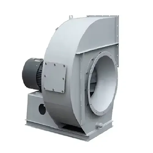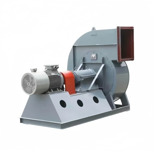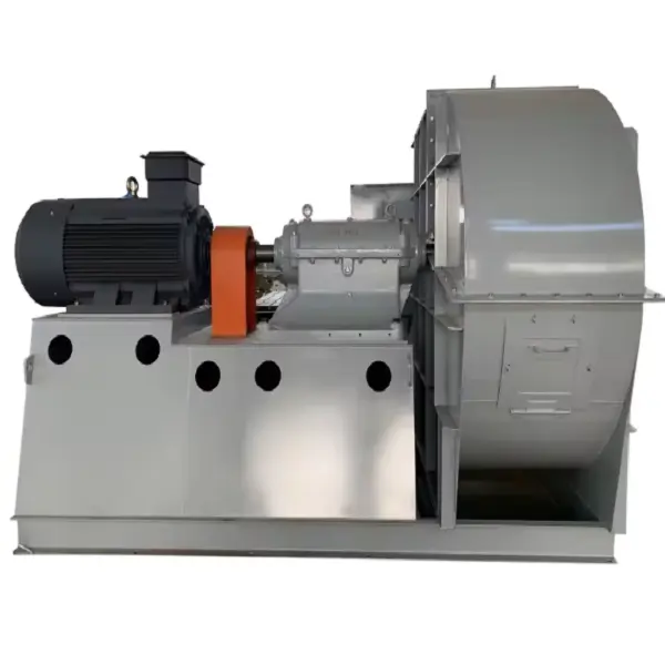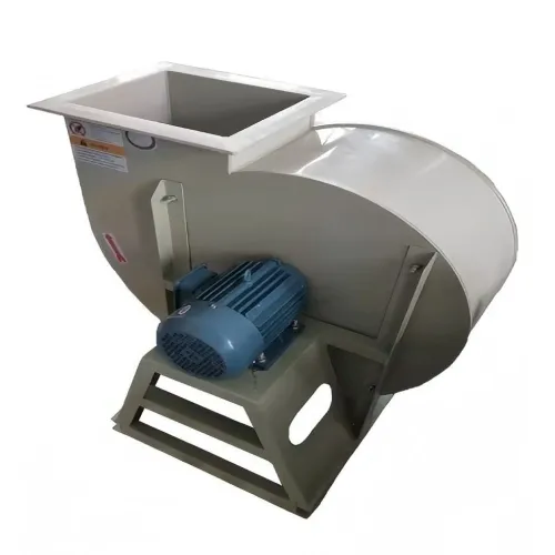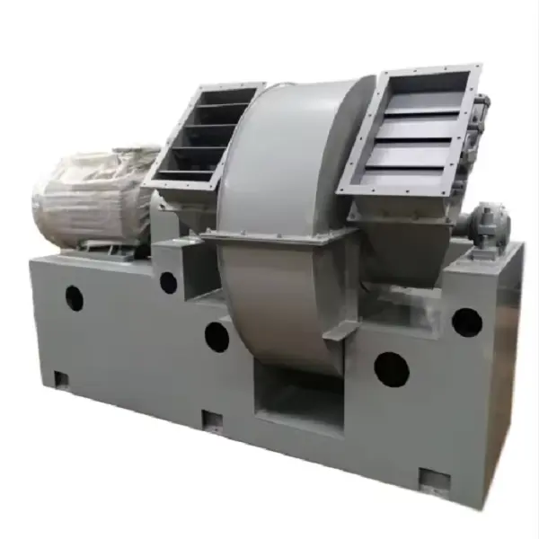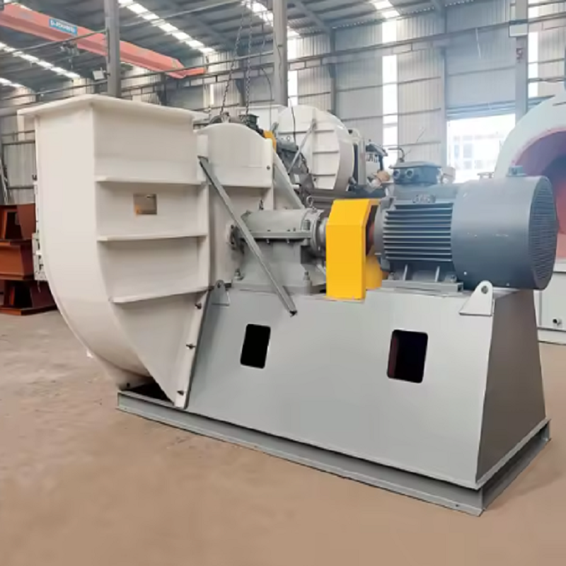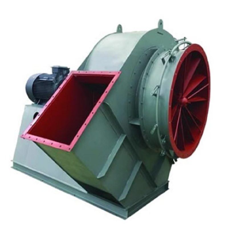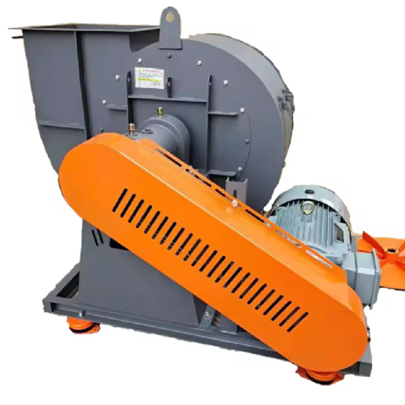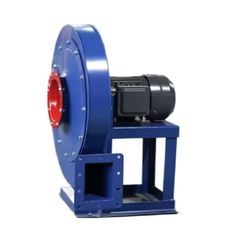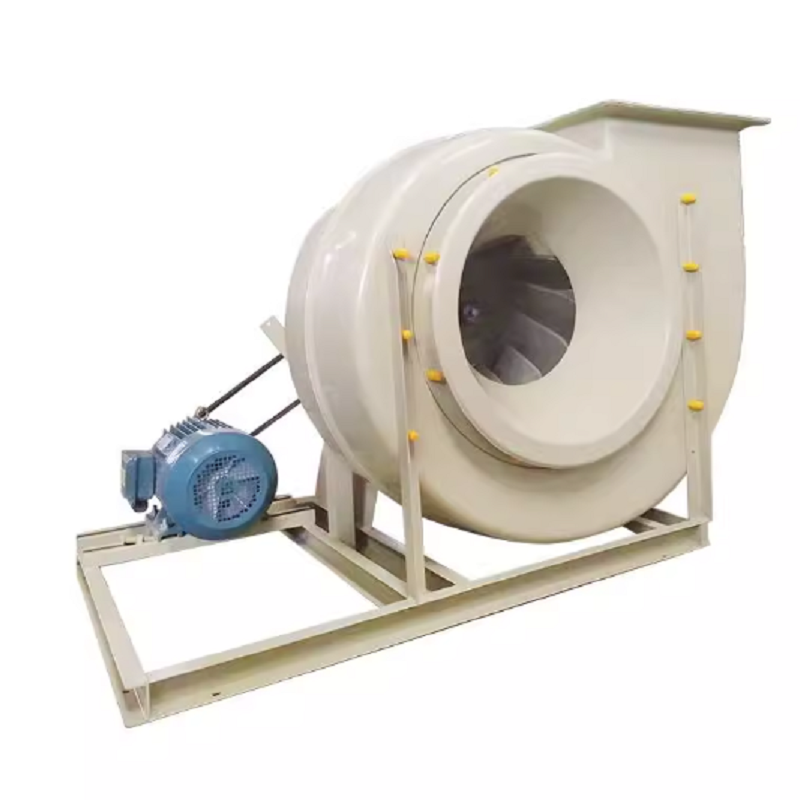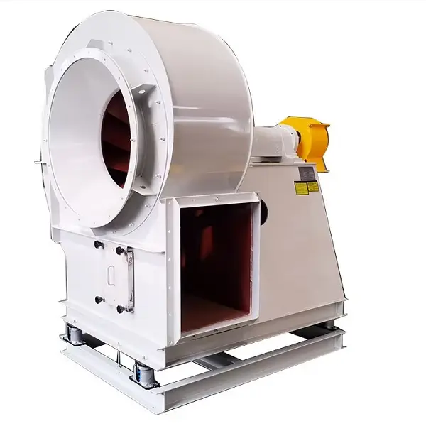
Rising electricity costs are making fan power consumption a more visible operating expense for industrial plants. In applications such as dust collection, boiler exhaust, process ventilation, drying, and material handling, fans may operate continuously for thousands of hours each year. This is increasing interest in High-Efficiency Industrial Centrifugal Fans, especially where airflow and pressure requirements remain high but plants need to control electricity consumption. The U.S. Department of Energy also emphasizes a system-level approach to fan efficiency rather than evaluating the fan alone.
A fan that runs 24 hours a day can consume a considerable amount of electricity even when its motor rating is relatively modest. For example, an 18.5 kW motor operating 20 hours per day for 300 days would theoretically consume about 111,000 kWh per year at full load. If the actual process only requires part of the rated airflow, operating the fan continuously at full speed can result in unnecessary energy consumption.
This is one reason High-Efficiency Industrial Centrifugal Fans are increasingly evaluated according to their actual operating point rather than simply their motor power. The important parameters are airflow, static or total pressure, fan efficiency, rotational speed, motor efficiency, and operating hours. A fan should be selected according to the required duty point, because an oversized fan may force operators to use dampers or inlet devices to restrict airflow.
A common mistake in industrial fan projects is adding excessive safety margins to airflow and pressure. For example, suppose a dust collection system actually requires 20,000 m³/h at 1,800 Pa, but the selected fan is designed for 24,000 m³/h at 2,200 Pa. The additional capacity may appear useful during the design stage, but if the production system normally operates at the lower duty point, the fan may spend much of its operating life away from its best efficiency region.
For High-Efficiency Industrial Centrifugal Fans, the first practical step should therefore be measuring the actual system resistance. Record airflow, fan inlet and outlet pressure, rotational speed, motor current, and damper position. Then compare these values with the fan performance curve. If the damper is frequently heavily closed, this can be a useful indication that the fan or impeller may be oversized. DOE guidance similarly identifies oversized fans and restricted dampers as areas worth investigating during fan-system assessments.
Speed control is another important consideration. Under the fan affinity laws, airflow changes approximately in proportion to speed, pressure changes with the square of speed, and power changes approximately with the cube of speed.
For example, consider a centrifugal fan operating at 1,000 rpm and consuming approximately 30 kW. If the process can operate correctly after reducing the speed to 900 rpm, the theoretical power relationship is:
P₂ / P₁ ≈ (N₂ / N₁)³
Therefore:
P₂ ≈ 30 × (900 / 1,000)³ ≈ 21.9 kW
This represents a theoretical reduction of about 8.1 kW. The actual result will depend on system resistance, fan characteristics, motor efficiency, transmission losses, and the control strategy, so this calculation should be treated as an engineering estimate rather than a guaranteed saving. Still, it shows why variable-speed operation can be valuable in High-Efficiency Industrial Centrifugal Fans when the process does not require full airflow all the time.
Consider a cement-processing dust collection system designed for 20,000 m³/h. During normal production, measurements show that the system operates at approximately 19,000–20,000 m³/h, while the fan is running at 1,000 rpm. The plant originally selected a larger fan because of concerns about future production expansion.
After reviewing the ductwork, filter pressure drop, and fan curve, engineers determine that the actual system does not require the original design margin. A VFD is then used to control fan speed according to the required system pressure instead of keeping the motor at constant speed and throttling the airflow with a damper.
This type of optimization can make High-Efficiency Industrial Centrifugal Fans more effective because the energy-saving potential comes from matching fan output to process demand. DOE's Better Plants program specifically recommends variable-speed control as one of the key measures for improving fan-system performance.
Replacing the fan is not always the first solution. A dirty filter, undersized duct, excessive elbows, sharp transitions, partially closed dampers, or poorly arranged inlet duct can increase system resistance. The fan then has to generate additional pressure to maintain the required airflow.
For example, if a filter originally produces 300 Pa of pressure loss but later reaches 650 Pa because of loading, the fan has to overcome an additional 350 Pa. If the system is already operating close to its pressure limit, airflow can decrease while motor energy consumption remains significant. This is why the performance of High-Efficiency Industrial Centrifugal Fans should always be evaluated together with the complete air system. DOE guidance recommends checking system effects such as duct routing, fittings, turns, and other sources of pressure loss rather than focusing only on individual components.
Fan efficiency does not depend only on the impeller. The complete power chain includes the motor, coupling or belt drive, bearings, fan aerodynamic efficiency, and control method. A highly efficient impeller connected to an inefficient transmission system may not deliver the expected overall energy performance.
When specifying High-Efficiency Industrial Centrifugal Fans, buyers should therefore request more than airflow and pressure. A useful technical specification should include the required duty point, fan efficiency, rotational speed, motor rating and efficiency, operating temperature, gas density, drive arrangement, and expected operating range. For variable-speed systems, the minimum and maximum operating speeds should also be defined.
A fan's maximum efficiency shown on a catalogue curve does not automatically mean that the installed system will operate at that efficiency. If the actual duty point is far away from the best efficiency region, energy consumption and vibration may increase, while control stability can become more difficult.
For High-Efficiency Industrial Centrifugal Fans, a practical commissioning procedure is to record at least three operating conditions—for example 80%, 100%, and 110% of normal airflow—and compare airflow, pressure, speed, motor current, and calculated shaft or electrical power. This creates a useful operating baseline for future maintenance. The DOE's MEASUR platform also provides fan-system assessment tools intended to evaluate different system configurations and energy-saving opportunities.
Efficiency can deteriorate even when the fan itself has not been redesigned. Belt slip, incorrect belt tension, bearing problems, impeller fouling, deposits on blades, excessive vibration, and changes in duct resistance can all affect actual performance.
For example, a dust-loaded impeller may gradually change its aerodynamic characteristics and increase vibration. Operators may compensate by increasing fan speed, which can raise power consumption. Regular inspection of the impeller, bearings, belts, inlet condition, and system pressure therefore becomes part of energy management, not simply preventive maintenance.
Before replacing an existing fan with High-Efficiency Industrial Centrifugal Fans, it is useful to calculate the annual energy cost based on actual operating conditions.
A simple calculation is:
Annual Energy Consumption = Input Power × Operating Hours
For example, if a fan consumes 45 kW and operates 6,000 hours per year:
45 × 6,000 = 270,000 kWh/year
If system optimization reduces the average electrical input to 36 kW:
36 × 6,000 = 216,000 kWh/year
The difference is 54,000 kWh/year. The actual financial saving depends on the plant's electricity tariff, demand charges, operating schedule, and whether the fan can maintain the required process performance at the lower power level.
A larger motor does not automatically make a fan system more reliable or efficient. If the impeller, casing, system resistance, and operating point are not properly matched, additional motor capacity may simply increase the available power without solving the underlying problem.
The selection of High-Efficiency Industrial Centrifugal Fans should begin with accurate operating data: required airflow, static pressure, gas temperature, gas composition, dust concentration, altitude, operating hours, and control requirements. For high-temperature or corrosive applications, material selection and bearing arrangement must also be considered because these factors can affect long-term performance and maintenance.
As energy costs become a larger part of industrial operating expenses, fan selection is increasingly being treated as a system-engineering issue. The most effective approach is not simply to purchase a fan with a higher advertised efficiency. It is to match the fan to the actual duty point, minimize unnecessary system resistance, use appropriate speed control, maintain the impeller and drive system, and regularly verify operating performance.
For plants operating large ventilation, dust collection, boiler, drying, or process-exhaust systems, High-Efficiency Industrial Centrifugal Fans can provide an opportunity to reduce energy consumption when the equipment and air system are correctly matched. A proper engineering assessment should compare the required airflow and pressure with measured operating data before any fan replacement or modification is made. DOE resources likewise recommend assessing the fan and the surrounding system together when identifying energy-saving opportunities.