News

Industrial Centrifugal Fan Design Adapts to Application-Specific Operating Conditions

2026-09-22 0 Leave me a message

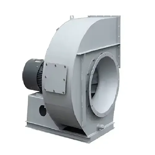
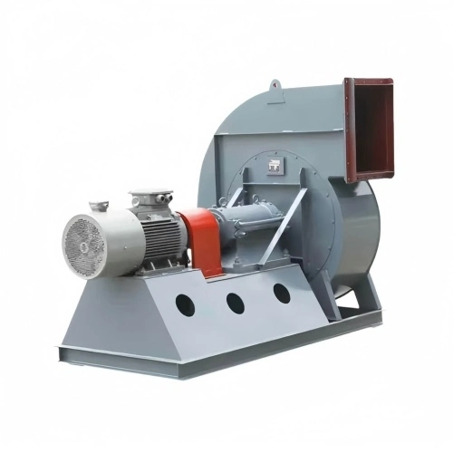
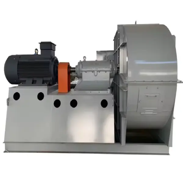
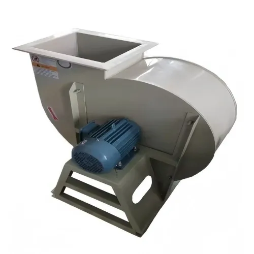
An Industrial Centrifugal Fan is rarely a simple “one-size-fits-all” piece of equipment. In an actual plant, the fan has to work against duct resistance, filters, dampers, scrubbers, heat exchangers, dust collectors, or other process equipment. At the same time, the gas may contain high-temperature air, abrasive dust, moisture, or corrosive components.

This is why fan selection should start with the actual operating condition rather than a standard model number. Airflow and pressure define the basic duty point, while temperature, gas composition, dust concentration, installation arrangement, operating hours, and control method determine how the fan should actually be built.

Start With the Real Duty Point

For an Industrial Centrifugal Fan, the first two parameters to confirm are airflow and pressure.

For example, suppose a dust collection system requires:

Airflow: 20,000 m³/h

Static pressure: 2,000 Pa

Gas temperature: 80°C

Continuous operation: 16 hours/day

Medium: air containing fine industrial dust

The specification should not simply say “20,000 m³/h fan.” The fan must be capable of delivering approximately 20,000 m³/h at the required system pressure.

This distinction is important because a centrifugal fan may deliver a large airflow when operating against very low resistance, but the actual airflow can fall significantly once filters, elbows, long ducts, dampers, and process equipment are connected.

A practical selection procedure is to calculate the pressure loss of each component separately and then determine the total system resistance. The fan performance curve should then be checked at the required operating point. The intersection between the fan curve and system curve determines the actual operating condition.

Do Not Size the Fan From Motor Power Alone

One common mistake in industrial projects is starting with motor power.

For example, a customer may request a 30 kW motor because the existing machine uses a 30 kW motor. That does not necessarily mean the replacement Industrial Centrifugal Fan should use the same motor.

The required motor power depends on airflow, pressure, gas density, fan efficiency, transmission efficiency, and operating speed. A change in duct resistance or gas temperature can therefore change the required shaft power even when the nominal airflow remains unchanged.

For a preliminary calculation, fan shaft power can be estimated from:

P ≈ Q × ΔP / (1000 × η)

where:

P = fan power in kW

Q = airflow in m³/s

ΔP = pressure in Pa

η = overall fan efficiency

The final motor should then be checked against the complete fan performance curve and actual operating range rather than relying only on a theoretical calculation.

This approach also helps prevent two opposite problems: selecting a motor that is too small for the worst operating condition, or installing an unnecessarily large motor that runs inefficiently for years.

Temperature Changes the Fan Design

Temperature is another parameter that should be confirmed before manufacturing an Industrial Centrifugal Fan.

A fan handling 40°C air and a fan handling 300°C flue gas may have completely different mechanical configurations even if their airflow and pressure requirements look similar.

High-temperature applications can require:

Heat-resistant impeller material

High-temperature bearings or bearing arrangements

Shaft cooling

Cooling discs

Thermal expansion allowances

Special seals

Heat-resistant coatings

Appropriate motor mounting arrangements

Consider a furnace exhaust application with a design temperature of 280°C. Installing a conventional fan designed for ambient air without considering heat transfer can result in excessive bearing temperature, shaft expansion, grease degradation, or motor overheating.

In such applications, the engineering team should confirm both the normal operating temperature and maximum temperature, rather than using only the average process temperature.

For example:

Normal temperature: 250°C

Maximum temperature: 300°C

is much more useful for fan engineering than simply stating “high-temperature gas.”

Temperature also affects gas density. Therefore, the airflow condition—actual volume flow or standardized volume flow—must be clearly defined before calculating fan performance and motor power.

Dust Determines Impeller Construction

The gas composition is equally important.

An Industrial Centrifugal Fan handling clean ventilation air can use a completely different impeller design from a fan handling abrasive dust from a cement plant, mineral processing line, or dust collector.

Fine dust may gradually accumulate on the impeller. Larger abrasive particles can erode the blade leading edges and reduce the impeller thickness over time.

For dusty applications, the following should be checked:

Particle size

Dust concentration

Particle hardness

Moisture content

Whether the dust is sticky

Operating hours

Required maintenance interval

For example, imagine a fan initially designed for 20,000 m³/h at 2,000 Pa. After several months, vibration increases and airflow decreases.

Instead of immediately changing the motor, technicians should inspect the impeller.

Possible causes include:

Dust accumulation

Blade erosion

Impeller imbalance

Loose components

Bearing problems

Belt misalignment

If dust has accumulated unevenly on the impeller, even a relatively small amount of buildup can create dynamic imbalance. Cleaning and rebalancing the impeller may solve the problem without replacing the entire fan.

Material Selection Must Follow the Gas Condition

Material selection should also be linked directly to the process medium.

A carbon-steel Industrial Centrifugal Fan may be suitable for ordinary ventilation, while corrosive exhaust may require stainless steel or another corrosion-resistant construction.

For chemical-process exhaust, the engineering team should identify the actual contaminants rather than simply describing the gas as “corrosive.”

For example, the gas may contain:

Water vapor

Acid mist

Chlorides

Fluorides

Sulfur compounds

Process dust

The combination of temperature, humidity and chemical concentration determines the actual corrosion risk.

In one practical design situation, a process fan handling hot humid gas containing acidic components may initially be proposed with 316L stainless steel. If the customer specifies a more aggressive chemical environment, the material requirement may need to be upgraded after reviewing the gas composition and corrosion conditions.

The important point is that stainless steel is not automatically the answer to every corrosion problem. Material selection should be based on the actual chemical environment and temperature.

Fan Speed Is a Design Parameter, Not Just a Number

The rotational speed of an Industrial Centrifugal Fan directly affects airflow, pressure and power.

Under similar operating conditions, the approximate fan laws are:

Airflow ∝ speed

Pressure ∝ speed²

Power ∝ speed³

This means a small increase in speed can have a much larger effect on motor power.

For example, if a fan operates at 1,000 rpm and is increased to 1,100 rpm:

Speed increase = 10%

Approximately:

Airflow increase ≈ 10%

Pressure increase ≈ 21%

Power increase ≈ 33%

That is why increasing fan speed should never be treated as a simple way to obtain more airflow.

If the original motor is already close to its rated load, a 10% speed increase can push the motor into an overload condition.

For variable-process applications, a VFD can provide better control by allowing the fan speed to follow actual process demand. However, the motor, bearings, impeller, balancing, and operating speed range must all be checked before implementing variable-speed operation.

Case Study: Solving an Airflow Problem Without Replacing the Fan

Consider an industrial exhaust system originally designed for:

Airflow: 20,000 m³/h

Pressure: 2,000 Pa

After commissioning, the measured airflow is only:

17,500 m³/h

The first reaction might be to select a larger Industrial Centrifugal Fan.

That is not necessarily the correct solution.

The engineering team should first measure the actual pressure at the fan inlet and outlet and check the system resistance.

During inspection, assume the following problems are found:

One filter has a much higher pressure drop than expected.

Several elbows have a poor-radius configuration.

The inlet duct is too close to the fan inlet.

The discharge damper is not fully open.

In this case, replacing the fan could simply hide a system-design problem.

After correcting the filter condition, improving the duct arrangement, and adjusting the damper, the system may return much closer to its original design point.

This is a useful lesson for industrial fan troubleshooting: a fan that cannot deliver the expected airflow is not automatically a fan-selection failure.

The entire air system must be checked.

Case Study: Excessive Airflow and Motor Load

Another common situation occurs when the measured airflow is higher than the design requirement.

Suppose an Industrial Centrifugal Fan was designed for:

20,000 m³/h at 2,000 Pa

but field measurements show:

24,000 m³/h at 1,700 Pa

The fan is moving approximately 20% more air than required.

The first items to check are:

Actual fan speed

Damper position

System resistance

Pulley diameter

Motor current

Fan operating point

If the fan is running faster than the original design speed, reducing the speed may bring the operating point back toward the required condition.

For a variable-speed fan, this can be tested gradually using the VFD while monitoring airflow, pressure, motor current, vibration and bearing temperature.

For a belt-driven fan, pulley dimensions should also be checked. A pulley replacement or incorrect pulley ratio can unintentionally increase fan speed.

Installation Details Can Affect Performance

Even a correctly selected Industrial Centrifugal Fan can perform poorly if the installation does not match the design.

Before commissioning, technicians should check:

Inlet duct alignment

Outlet duct arrangement

Flexible connections

Damper position

Belt tension

Pulley alignment

Shaft alignment

Bearing lubrication

Foundation bolts

Impeller clearance

Rotation direction

For belt-driven equipment, incorrect belt tension can cause slip, excessive bearing load or unstable fan speed.

For direct-drive equipment, shaft alignment and coupling condition become more important.

The fan should also be checked for abnormal vibration immediately after startup and again after reaching normal operating temperature.

Design the Fan Around the Process

The most reliable Industrial Centrifugal Fan is not necessarily the largest fan or the one with the highest motor power. It is the fan whose aerodynamic performance, materials, mechanical construction and control system match the actual process.

Before issuing a purchase order, the technical specification should ideally include:

Required airflow

Static or total pressure

Gas temperature

Maximum temperature

Gas composition

Dust concentration

Particle characteristics

Altitude

Operating hours

Fan speed

Motor power and voltage

Drive arrangement

Installation orientation

Ambient conditions

Control method

Required inspection and testing documents

A complete specification gives the manufacturer enough information to select the impeller, casing, shaft, bearings, motor and drive arrangement correctly.

For industrial projects, this is much more effective than selecting a fan simply by airflow or motor power. The system operating point and process conditions should determine the fan design from the beginning..

Final Takeaway

An Industrial Centrifugal Fan should be designed around the actual process rather than treated as a standard catalog product.

Airflow and pressure define the basic duty point. Temperature determines the thermal design. Dust affects impeller construction and wear protection. Corrosive gases influence material selection. Fan speed affects both performance and power consumption. Finally, duct layout and installation quality determine whether the selected fan can actually reach its design point in the field.

For engineers and purchasing teams, the most useful approach is simple: define the complete operating condition first, select the fan second, and verify the performance after installation.

That process reduces the risk of low airflow, motor overload, excessive vibration, premature wear and unnecessary energy consumption—and it provides a much more reliable basis for long-term industrial fan operation.

Related News
Leave me a message
X
We use cookies to offer you a better browsing experience, analyze site traffic and personalize content. By using this site, you agree to our use of cookies. Privacy Policy
RejectAccept