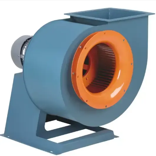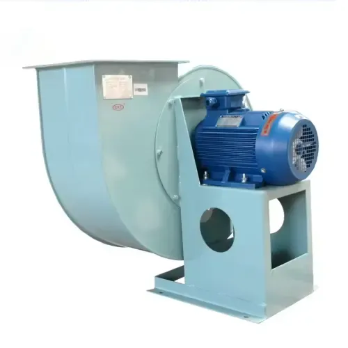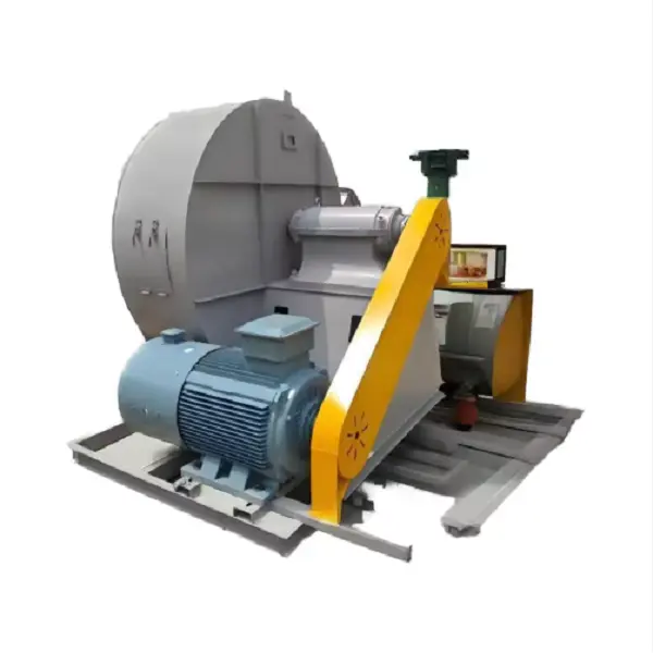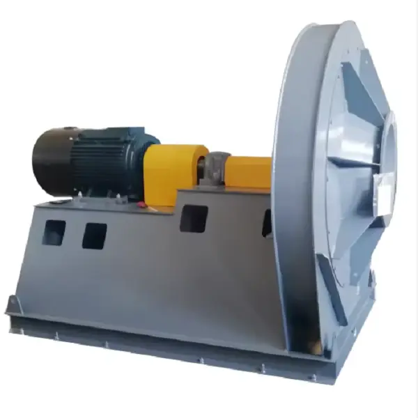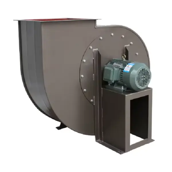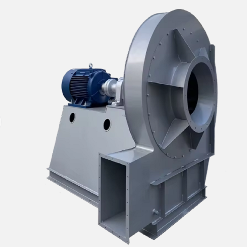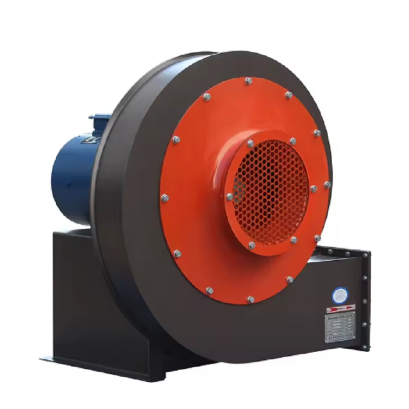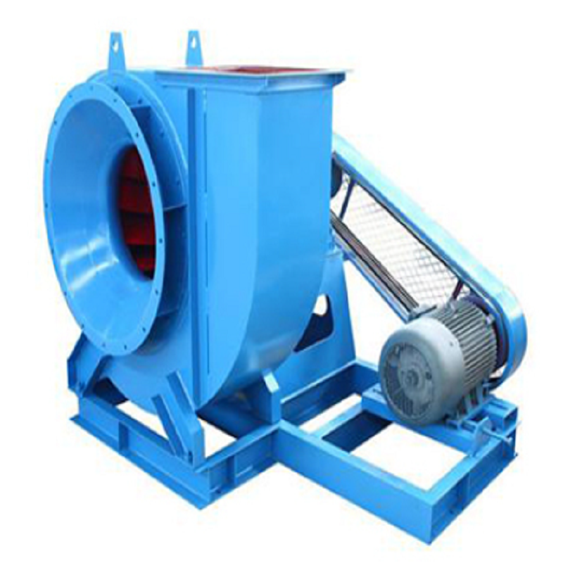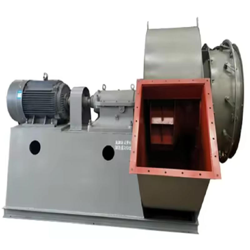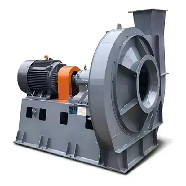
In an industrial boiler, the induced draft fan is often treated as a simple exhaust device. In practice, it is one of the key pieces of equipment controlling furnace pressure, flue gas movement, combustion stability, and auxiliary power consumption. A properly selected Industrial Boiler Induced Draft Fan must move the required flue gas volume while overcoming the resistance of the boiler, ductwork, dust collector, scrubber, chimney, and other downstream equipment.
The mistake I see most often is selecting an Industrial Boiler Induced Draft Fan based only on boiler capacity or motor power. A 10 MW boiler, for example, does not automatically require a particular fan size. The actual operating point depends on flue gas volume, gas temperature, system resistance, fuel, excess air, dust concentration, and the pressure required at the furnace outlet.
The first step in selecting an Industrial Boiler Induced Draft Fan is to determine the actual gas volume at the fan inlet.
This is important because flue gas temperature changes its density significantly. A volume calculated at standard conditions cannot simply be used as the fan operating volume without correction.
For example, assume a boiler produces 30,000 Nm³/h of flue gas at standard conditions and the gas temperature at the fan inlet is 180°C. The approximate actual volume can be estimated from:
Q₂ = Q₁ × (T₂ / T₁)
where temperatures are in Kelvin.
Using 20°C as the reference:
30,000 × (453 / 293) ≈ 46,350 m³/h
This is a substantial difference.
If the fan is selected using 30,000 m³/h instead of approximately 46,350 m³/h at the actual operating temperature, the installed fan may not provide the expected draft.
For an Industrial Boiler Induced Draft Fan, the quotation data should therefore specify whether the airflow is given in Nm³/h, Sm³/h, or actual m³/h, together with the corresponding gas temperature and pressure.
Fan pressure is just as important as airflow.An Industrial Boiler Induced Draft Fan has to overcome the resistance of the complete flue gas route. This may include boiler gas passages, economizers, air preheaters, cyclones, bag filters, ESPs, scrubbers, dampers, elbows, expansion sections, ducts, and the chimney.
A practical pressure calculation can be arranged as:
ΔPtotal = ΔPboiler + ΔPduct + ΔPequipment + ΔPdamper + ΔPstack
The calculation should be performed at the design gas condition.
Consider a system with:
Boiler and heat-transfer section: 850 Pa
Ductwork and elbows: 450 Pa
Bag filter: 1,200 Pa
Damper and transition sections: 250 Pa
Chimney and outlet losses: 350 Pa
The total estimated resistance is:
850 + 450 + 1,200 + 250 + 350 = 3,100 Pa
The engineer should then establish an appropriate design margin based on the project requirements rather than arbitrarily adding a large percentage.
This is why two boilers with similar capacities can require completely different Industrial Boiler Induced Draft Fan models.
Dust is one of the biggest differences between a boiler exhaust fan and a clean-air ventilation fan.
A biomass boiler, coal-fired boiler, waste-fired boiler, and gas-fired boiler can have very different dust characteristics. Fly ash can gradually erode the impeller, while sticky particles can accumulate on the blades.
Impeller buildup creates another problem: imbalance.
For example, if only a few hundred grams of material accumulate unevenly on a large impeller, the mass distribution changes. The resulting centrifugal force increases rapidly with rotational speed.
For this reason, an Industrial Boiler Induced Draft Fan operating with dusty flue gas should be inspected periodically for:
Impeller ash accumulation
Blade erosion
Leading-edge wear
Shaft condition
Bearing temperature
Vibration
Casing deposits
Expansion-joint leakage
If vibration gradually increases after several months of operation, replacing the motor is usually not the first thing to do. The impeller and operating conditions should be checked first.
A large fan does not automatically mean a more efficient fan.An Industrial Boiler Induced Draft Fan should operate close to the required duty point on its performance curve. If the actual system requires 40,000 m³/h at 3,000 Pa but the selected fan is designed around a very different operating point, the system may rely heavily on dampers to control airflow.
A damper reduces flow by adding resistance. The fan still produces pressure, but part of that pressure is simply dissipated across the damper.
For continuous boiler operation, this is often an inefficient way to control a variable load.
Variable-speed control provides a better approach when the operating range justifies it. Fan affinity laws indicate that, under comparable conditions:
Q ∝ N
ΔP ∝ N²
P ∝ N³
Therefore, reducing fan speed can produce a much larger reduction in power than reducing airflow alone.
For example, reducing speed to 80% of the original speed gives approximately:
Power ratio = 0.8³ = 0.512
The theoretical fan power becomes about 51% of the original value, assuming the operating conditions remain within the applicable fan-law range.
Actual savings depend on the system curve, motor efficiency, VFD losses, and operating point, so this should be treated as an engineering estimate rather than a guaranteed 49% reduction.
Many boilers do not operate continuously at 100% load.
During periods of reduced production, the required flue gas volume decreases. If the Industrial Boiler Induced Draft Fan continues operating at full speed while a damper controls the draft, electrical power can be unnecessarily high.
A better control strategy is to measure furnace or flue-gas static pressure and adjust fan speed according to the required draft.
A typical control sequence is:
Boiler load → Draft pressure sensor → PID controller → VFD → ID Fan speed
The control target should not simply be “maximum suction.” Excessive negative pressure can introduce additional air into the furnace or affect combustion conditions.
The objective is controlled negative pressure, not the largest possible negative pressure.
A VFD-based ID fan control strategy has also been documented in boiler applications as a way to match fan speed more closely to the required flue pressure and reduce unnecessary airflow and electrical losses.
Consider a biomass boiler with the following operating conditions:
Boiler capacity: approximately 12 t/h steam
Flue gas flow: 42,000 m³/h
Fan inlet temperature: 165°C
Required total pressure: approximately 2,800 Pa
Existing motor: 75 kW
Existing fan speed: 1,480 rpm
Control method: inlet damper
Operating load: normally 60–90%
The plant reported that the fan motor frequently operated near its rated current even when boiler production was below maximum capacity.
The first inspection found no obvious bearing failure. The impeller was also structurally acceptable.
The problem was traced to the control method.
At approximately 65% boiler load, the fan was still running close to full speed, while the inlet damper was significantly closed. The fan was therefore producing more pressure than the system required, and the damper was converting part of that pressure into additional resistance.
The recommended modification was to install a VFD and control the ID fan according to furnace draft pressure.
After commissioning, the operating procedure was changed so that the fan speed followed boiler load and draft pressure rather than remaining near maximum speed.
The important lesson from this case is that replacing the fan with a larger or more powerful model would not have solved the problem. The existing Industrial Boiler Induced Draft Fan had sufficient capacity; the problem was the control strategy.
Temperature is another parameter that should be confirmed before selecting an Industrial Boiler Induced Draft Fan.
When flue gas temperature increases, gas density decreases. At the same mass flow, the actual volumetric flow becomes larger.
High temperature also affects:
Shaft thermal expansion
Bearing arrangement
Lubrication
Casing expansion
Material selection
Coupling arrangement
Motor location
Cooling requirements
Sealing arrangement
For higher-temperature applications, the fan structure should therefore be designed around the actual inlet temperature rather than simply selecting a standard fan and assuming that it can handle hot gas.
If the temperature changes substantially between startup and normal operation, thermal expansion should also be considered during shaft, bearing, and coupling alignment.
When an Industrial Boiler Induced Draft Fan cannot maintain the required furnace negative pressure, do not immediately assume that the fan is undersized.
A practical troubleshooting sequence is:
Confirm the motor frequency, rotational speed, and VFD output.
If the damper is nearly fully open and draft remains insufficient, the fan may be undersized or system resistance may have increased.
If the damper is heavily throttled, the problem may instead be excessive fan capacity or an inappropriate control strategy.
Check the pressure drop across:
Boiler
Economizer
Air preheater
Cyclone
Bag filter
Scrubber
Main duct
Damper
A dirty bag filter can substantially increase system resistance.
Look for ash accumulation, erosion, cracks, deformation, and blade damage.
Increasing vibration may indicate imbalance, misalignment, bearing deterioration, looseness, or buildup on the impeller.
Record:
Airflow
Static pressure
Fan speed
Motor current
Motor power
Gas temperature
Furnace pressure
Vibration
This data is much more useful than simply saying that “the fan suction is weak.”
Oversizing is sometimes treated as a safe option because engineers assume that “more capacity is better.”
It is not always better.
If an Industrial Boiler Induced Draft Fan is substantially oversized, the system may require aggressive damper throttling. This increases pressure loss and can raise electrical consumption.
Excessive draft can also disturb the intended combustion conditions.
A better approach is to establish the normal operating point, maximum operating point, minimum expected load, and future operating requirements before selecting the fan.
For example, if the boiler normally operates between 60% and 90% load, selecting a fan based only on an extreme theoretical maximum may result in a machine that spends most of its operating life away from its best-efficiency region.
The performance of an Industrial Boiler Induced Draft Fan cannot be evaluated separately from the boiler exhaust system.
A technically correct fan selection should consider:
Boiler → Heat-transfer equipment → Dust collector → Ductwork → ID Fan → Chimney
If a new bag filter is installed later, its pressure drop can change the operating point of the existing fan. Likewise, adding a scrubber, changing fuel, increasing boiler capacity, or modifying the chimney can all change the required fan duty.
This is why fan selection should be based on the complete system resistance rather than simply matching an old fan model.
An efficient Industrial Boiler Induced Draft Fan is not simply a high-power centrifugal fan. Its real performance depends on whether airflow, pressure, temperature, dust loading, impeller design, control method, and system resistance have been correctly matched.
For new installations, calculate the actual flue gas volume and total pressure loss before selecting the fan. For replacement projects, collect operating data before deciding that the existing fan is undersized. For variable-load boilers, evaluate VFD control instead of relying entirely on dampers.
In practical operation, the biggest gains often come from relatively simple actions: cleaning the impeller, correcting excessive system resistance, repairing duct leakage, maintaining proper furnace draft, and matching fan speed to actual boiler load.
The goal is not to make the Industrial Boiler Induced Draft Fan run harder. The goal is to make it deliver exactly what the boiler needs—with the lowest reasonable energy consumption and stable operation over the full load range.