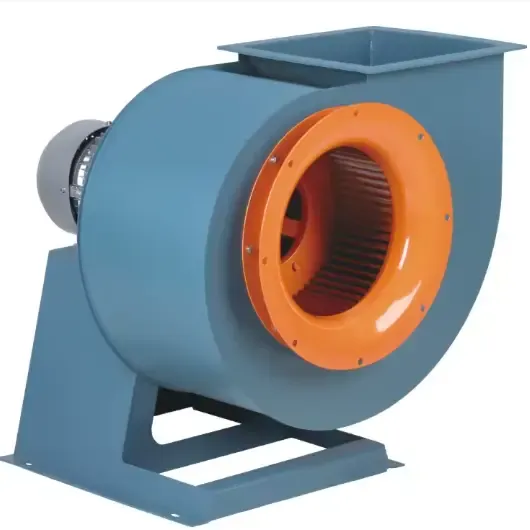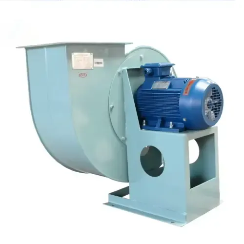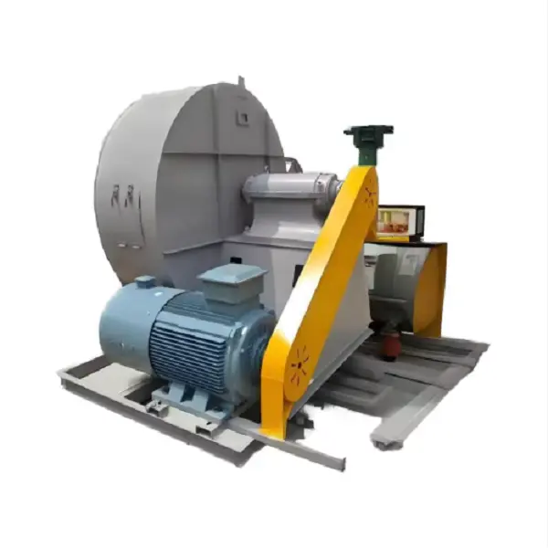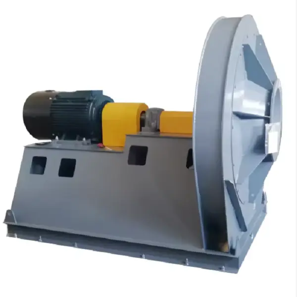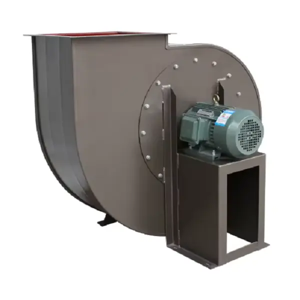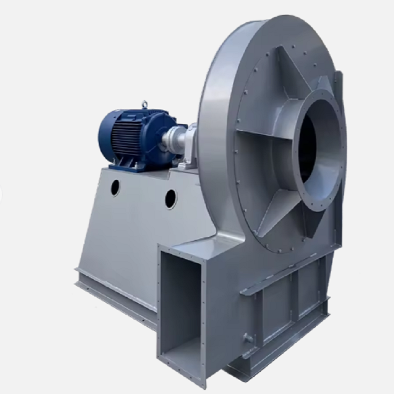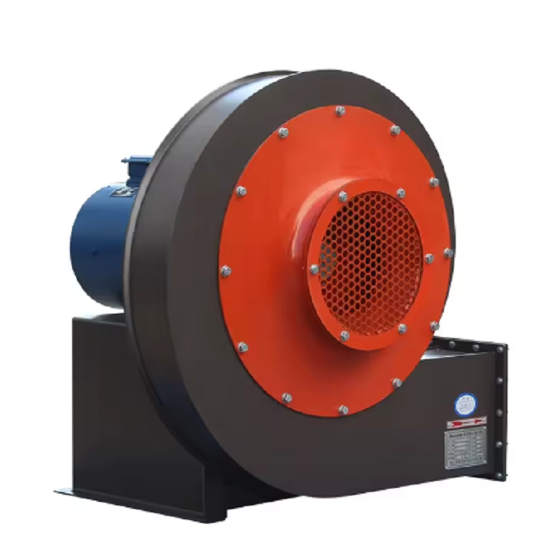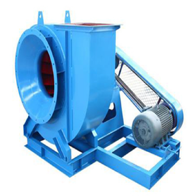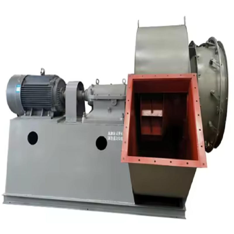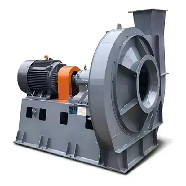
Boiler performance is closely related to the stability of the air and flue gas system. If the combustion air supply is insufficient or the flue gas cannot be discharged smoothly, operators may see unstable flame conditions, higher fuel consumption, furnace pressure fluctuations, and increased emissions. In these systems, Centrifugal Fans are commonly used because they can generate the pressure required to overcome resistance from ducts, economizers, air preheaters, dust collectors, dampers, and other boiler equipment.
For boiler applications, selecting Centrifugal Fans is not simply a matter of matching the motor power to the boiler capacity. The fan has to operate at the required airflow and pressure under the actual gas temperature and operating conditions. A fan that provides adequate airflow at low resistance may fail to maintain the required furnace draft when the system resistance increases. Conversely, selecting excessive pressure can result in unnecessary energy consumption and unstable control. The first step is therefore to establish the actual operating point before choosing the fan.
A typical industrial boiler may use fans for several different duties. Forced draft fans supply combustion air to the furnace, induced draft fans remove flue gas from the furnace and maintain negative pressure, while primary or secondary air fans may be used in specific combustion systems. Although these applications have different operating duties, Centrifugal Fans are widely used because their pressure-producing capability makes them suitable for systems with significant resistance.
For an induced draft application, the fan must overcome the pressure losses through the furnace outlet, convection sections, economizer, air preheater, ductwork, cyclone or bag filter, chimney, and dampers. If the total resistance is underestimated during selection, the actual airflow can be considerably lower than expected after commissioning. This is one of the most common reasons why Centrifugal Fans appear to be “underperforming” even though the motor and impeller are operating normally.
Temperature also needs to be included in the calculation. Hot flue gas has a lower density than ambient air, so the relationship between volumetric flow, mass flow, pressure, and fan power changes with temperature. For example, a flue gas system designed for 180°C should not simply use the same density assumptions as a 20°C air-handling system. When selecting Centrifugal Fans, the engineer should confirm gas temperature, altitude, moisture content, gas composition, and whether the stated pressure is static pressure or total pressure.
One practical mistake during fan selection is providing only the required airflow. For example, a specification such as “20,000 m³/h fan” is not sufficient to select Centrifugal Fans. Several fan models can provide 20,000 m³/h, but their pressure capabilities may differ significantly.
A more useful specification would be something like:
Airflow: 20,000 m³/h
Required pressure: 2,500 Pa
Gas temperature: 180°C
Medium: boiler flue gas
Operating altitude: 500 m
Dust concentration: specified according to the process
Required operating hours: continuous
Motor supply: according to the plant electrical system
With these parameters, the fan manufacturer can evaluate the operating point against the fan performance curve. The selected Centrifugal Fans should preferably operate in a stable region of the curve rather than at the extreme left or right side. A reasonable operating margin can also be considered, but simply adding a large pressure margin is not a good engineering practice because it can increase motor power and throttling losses.
A boiler system rarely operates exactly as it did during the original design calculation. Filters accumulate dust, heat-transfer surfaces become fouled, dampers are adjusted, ductwork may be modified, and fuel characteristics can change. Each of these factors can affect system resistance.
Consider an induced draft system originally designed for 25,000 m³/h at 3,000 Pa. After several months of operation, the bag filter differential pressure increases because of dust loading. The fan speed remains unchanged, but the system resistance moves upward. The operating point of the Centrifugal Fans therefore shifts along the fan curve, potentially reducing airflow.
In this situation, increasing motor size is not necessarily the correct solution. The maintenance team should first measure filter differential pressure, damper position, fan inlet and outlet pressure, fan speed, motor current, and actual airflow. If the filter resistance is significantly higher than the original design value, cleaning or replacing the filter may restore performance without modifying the fan.
During commissioning, operators should record more than motor current and vibration. For Centrifugal Fans, a useful commissioning record should include fan speed, inlet pressure, outlet pressure, airflow, gas temperature, bearing temperature, motor current, and damper position.
The measurement sequence can be kept simple:
Confirm the impeller rotates in the correct direction.
Check that inlet and outlet dampers are in the correct commissioning position.
Start the fan according to the approved operating procedure.
Gradually move the damper while monitoring motor current.
Measure airflow and pressure at several stable operating points.
Compare the measured values with the manufacturer's performance curve.
Record vibration and bearing temperature after the system reaches a stable condition.
This process gives operators a baseline for future troubleshooting. If the same Centrifugal Fans show a gradual increase in vibration or motor current several months later, the original commissioning data provides a useful reference instead of relying on subjective observations.
A practical example can be seen in a biomass-fired industrial boiler. The boiler's induced draft system was originally designed for approximately 30,000 m³/h of flue gas. During initial operation, the furnace draft was stable. After several months, however, operators noticed that furnace pressure became increasingly difficult to control when the boiler approached full load.
The first assumption was that the Centrifugal Fans had insufficient capacity. Instead of immediately changing the fan, the maintenance team measured the system step by step.
The results showed that fan speed was close to the original value, motor current was within the expected range, and vibration had not increased significantly. However, the pressure drop across the downstream dust-collection equipment was substantially higher than the commissioning value.
The dust collector was inspected and found to have excessive pressure loss caused by fouled filter elements. After the filter elements were cleaned and the system resistance returned closer to the original design condition, the induced draft fan recovered the required airflow and furnace pressure became stable again.
The important lesson from this case is that Centrifugal Fans should not be judged independently from the system. A fan, duct, filter, damper, and chimney form one aerodynamic system. Changing the fan without identifying the actual source of resistance can increase project cost without solving the underlying problem.
Another common misconception is that a larger motor automatically means a more powerful fan. Motor power only tells part of the story. The actual performance of Centrifugal Fans depends on impeller diameter, impeller width, blade geometry, rotational speed, gas density, system resistance, and aerodynamic efficiency.
Fan affinity laws are useful when evaluating changes in speed. Under comparable conditions:
Airflow is approximately proportional to fan speed.
Pressure is approximately proportional to the square of fan speed.
Power is approximately proportional to the cube of fan speed.
This means a relatively small increase in speed can produce a substantial increase in power demand. For example, increasing fan speed by 10% can increase theoretical power demand to roughly 1.33 times the original value, assuming the same gas density and similar operating conditions.
For this reason, overspeeding Centrifugal Fans to compensate for an incorrectly designed or increasingly resistant system should not be treated as a permanent solution. The electrical load, impeller stress, shaft speed, bearing condition, and allowable operating range must all be checked.
Boiler flue gas can contain ash, dust, corrosive compounds, and moisture. These conditions affect the mechanical design of Centrifugal Fans.
For dusty gas, one important consideration is impeller wear. High-velocity particles can gradually erode blade surfaces, particularly around the leading edge. If the boiler burns abrasive fuel, the fan may require wear-resistant materials or replaceable wear plates.
High-temperature service creates another set of problems. Shaft expansion, bearing temperature, lubricant selection, thermal insulation, and cooling arrangements must be considered. Depending on the design, the bearing arrangement may need to be separated from the hot gas path.
Material selection should also be based on the actual gas composition rather than temperature alone. If sulfur compounds, chlorides, moisture, or other corrosive components are present, standard carbon steel may not provide adequate service life. In such conditions, the construction material and surface protection of Centrifugal Fans should be selected according to the actual operating environment.
Vibration is one of the most useful indicators of fan condition. However, simply observing that a fan is vibrating is not enough to identify the cause.
For Centrifugal Fans, maintenance personnel should first determine whether vibration is associated with rotational speed. Common causes include impeller imbalance, material accumulation on the blades, shaft misalignment, loose foundation bolts, bearing deterioration, coupling problems, and structural resonance.
In boiler applications, ash accumulation on the impeller deserves particular attention. Even a relatively small amount of uneven buildup can create dynamic imbalance. The vibration may become worse as fan speed increases.
A practical maintenance procedure is to record vibration at the drive-end and non-drive-end bearings in horizontal, vertical, and axial directions. The readings should be compared with previous records. A sudden change from the established baseline is often more meaningful than an isolated value.
Before balancing an impeller, technicians should also inspect the impeller for cracks, deformation, corrosion, and material buildup. Dynamic balancing should be carried out according to the applicable balancing requirements after mechanical defects have been addressed.
Energy consumption is another major consideration when operating Centrifugal Fans. In a boiler plant running continuously, even a relatively small reduction in fan power can produce meaningful annual savings.
The first step is to determine whether the fan is operating at the required airflow. If the process requires 80% of the design airflow but the fan continuously supplies 100%, the excess airflow may represent avoidable energy consumption.
Variable frequency drives can be useful when the boiler load changes significantly. Instead of controlling airflow primarily through a throttled damper, fan speed can be adjusted to match the required operating condition. Because fan power changes approximately with the cube of speed, reducing speed can provide substantial energy savings.
However, VFD installation should not be treated as an automatic energy-saving measure. The actual system curve, minimum required airflow, motor characteristics, fan operating range, and process control requirements should be evaluated first. Properly applied, speed control can make Centrifugal Fans much more responsive to changing boiler loads.What Should Be Included in a Fan Specification?When requesting a quotation for boiler Centrifugal Fans, providing complete operating information can significantly reduce the risk of selecting an unsuitable model.
At minimum, the technical specification should include:
Required airflow
Static or total pressure
Gas temperature
Gas composition
Dust concentration
Gas density or operating pressure
Installation altitude
Fan speed or maximum allowable speed
Motor voltage and frequency
Operating mode
Rotation direction
Fan arrangement
Material requirements
Bearing arrangement
Noise requirements, if applicable
Vibration and balancing requirements
If the application involves high-temperature flue gas, the supplier should also know whether the stated airflow is based on actual operating temperature or standard conditions. This distinction is important because a value in Nm³/h and a value in actual m³/h are not interchangeable.
The performance of a boiler exhaust system depends on much more than the fan itself. Correct aerodynamic selection, suitable materials, proper installation, commissioning measurements, and condition-based maintenance all contribute to reliable operation. Well-selected Centrifugal Fans can provide stable airflow and pressure while supporting combustion control and efficient flue gas removal.
For engineers selecting or replacing Centrifugal Fans, the most important starting point is the actual operating point: airflow, pressure, temperature, gas composition, and system resistance. Once these parameters are established, the fan performance curve, impeller design, motor power, material selection, and control method can be evaluated systematically.
In boiler applications, the cheapest fan is rarely the lowest-cost solution over its service life. A fan that operates close to its intended duty point, withstands the actual gas conditions, and can be maintained without excessive downtime will generally provide much better long-term value.