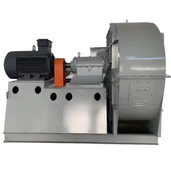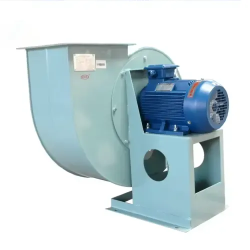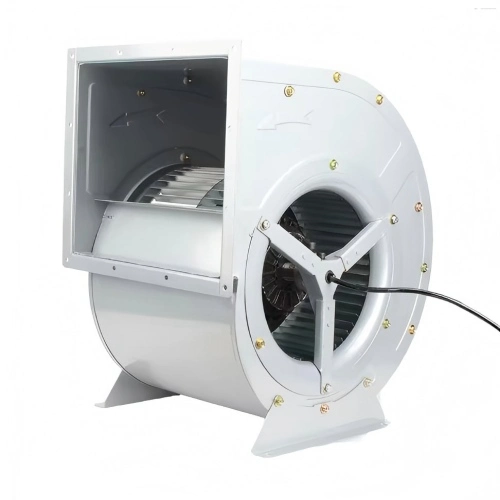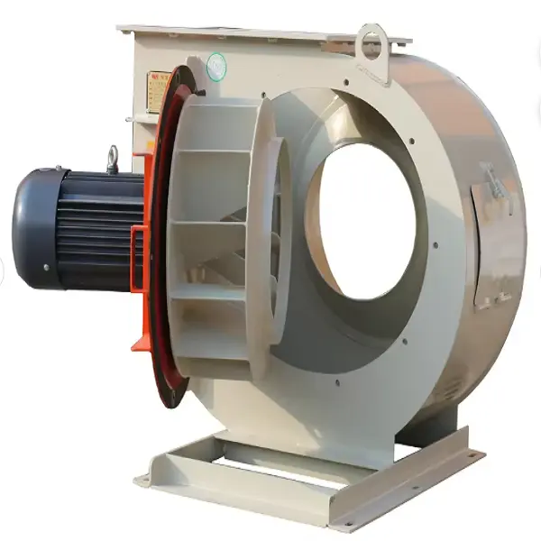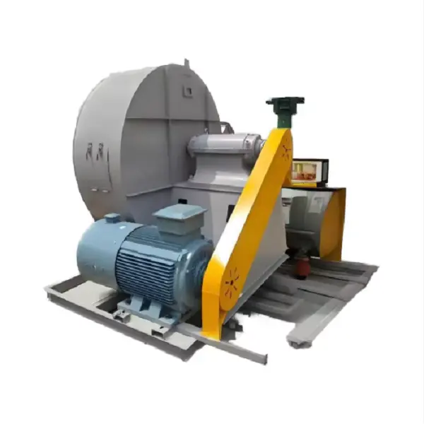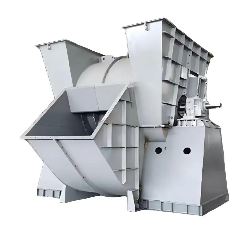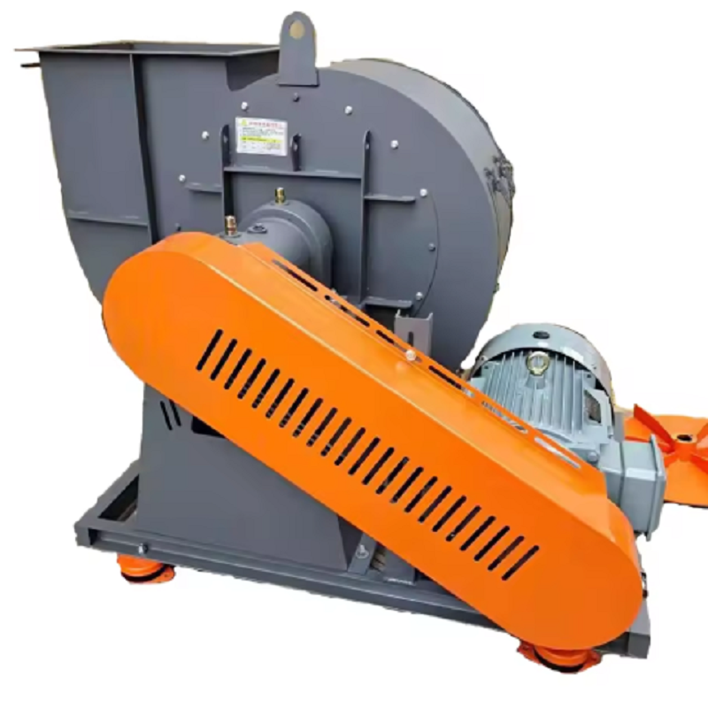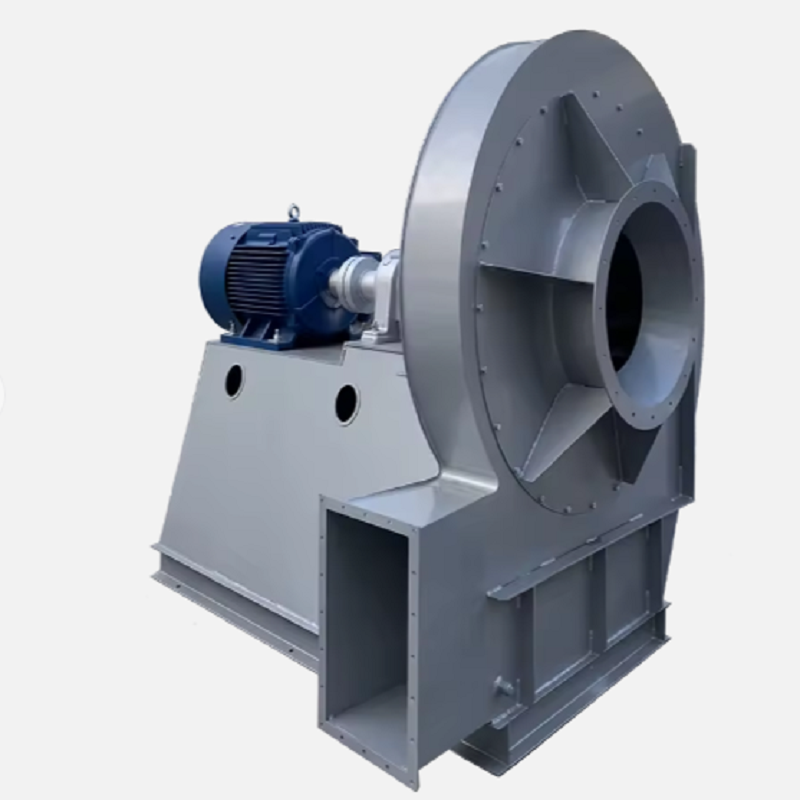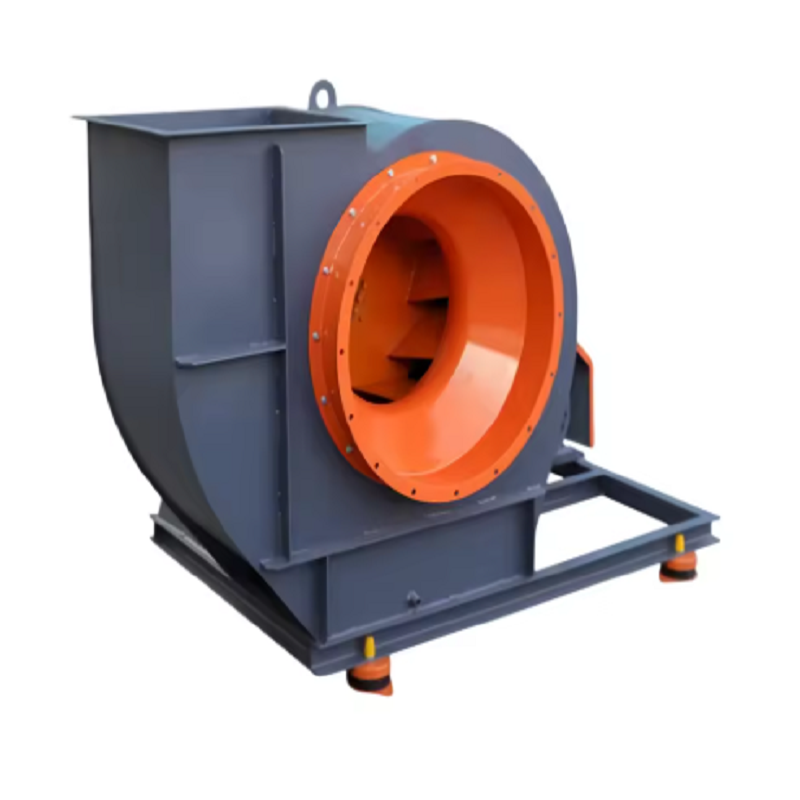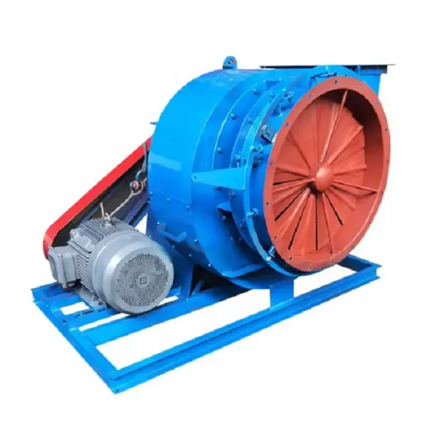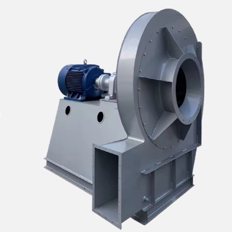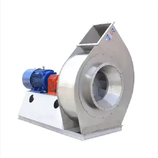
In an industrial boiler, combustion stability depends on more than the burner itself. The combustion system must receive the right amount of air at the required pressure, even when the boiler load changes. Boiler Forced Draft Fans provide this combustion air by pushing ambient or preheated air toward the burner, windbox, grate, or furnace. In balanced-draft systems, the forced draft fan works together with the induced draft fan to control airflow through the boiler.
Fuel cannot burn efficiently if the available oxygen is insufficient. At the same time, simply supplying more air is not a solution. Excess air absorbs heat and carries additional heat out through the stack, which can reduce boiler efficiency. For this reason, Boiler Forced Draft Fans need to provide sufficient airflow over the entire operating range rather than simply producing the maximum possible air volume.
For example, consider a biomass boiler operating between 60% and 100% load. If the fan runs at nearly full speed regardless of boiler load, the system may receive excessive combustion air at low load. The better approach is to control airflow according to actual fuel demand, using an inlet damper, inlet guide vane, or VFD depending on the system design. Research on boiler-house variable-speed control has also shown the relationship between fan operation, excess air, and boiler efficiency.
One of the most common mistakes when replacing a boiler fan is asking for a 30 kW, 45 kW, or 75 kW motor and expecting the fan manufacturer to determine everything from that number. Motor power is an output of the fan selection process, not the primary selection parameter.
For Boiler Forced Draft Fans, the basic information should include:
Required airflow, such as m³/h or CFM
Required static pressure or total pressure
Air inlet temperature
Fuel type
Boiler capacity
Operating altitude
Expected load range
Duct and equipment pressure losses
Burner or grate resistance
Air preheater pressure drop, if installed
Control method
Motor voltage and frequency
Fan installation arrangement
Rotation direction and outlet position
The pressure requirement should be calculated from the complete air path. Ducts, elbows, dampers, filters, air preheaters, windboxes, burner registers, and other components all contribute resistance.
Suppose an industrial boiler requires 18,000 m³/h of combustion air at 2,200 Pa static pressure under the design operating condition. The fan should not be selected simply as an “18,000 m³/h fan.”
First, the engineer should confirm whether 18,000 m³/h is the actual required operating airflow or whether it already includes the required design margin. Next, the pressure losses between the fan inlet and the furnace need to be calculated.
For example:
Air duct loss: 300 Pa
Damper loss: 180 Pa
Air preheater loss: 450 Pa
Windbox and burner loss: 700 Pa
Other system losses: 350 Pa
Required margin: evaluated separately according to the project design
The fan selection should then be checked against the resulting duty point rather than against airflow alone. This is particularly important when Boiler Forced Draft Fans are being used as replacements for an existing unit, because changes to the ductwork or burner can shift the actual operating point.
A fan can produce a large airflow at low pressure and still fail to deliver the required air to the furnace. Conversely, selecting excessive pressure can result in unnecessary throttling and higher operating power.
This is why the fan performance curve is important. The design point should be located within a suitable region of the fan curve, with enough control range for normal boiler operation.
For Boiler Forced Draft Fans, I would normally check at least three operating points:
Minimum stable boiler load
Normal operating load
Maximum continuous load
If the boiler normally operates at 70–90% load, the fan should not be optimized only for a theoretical 100% point. The actual operating range matters because combustion air demand changes with fuel input.
Variable-frequency drives are often considered for Boiler Forced Draft Fans because fan speed can be adjusted according to boiler load. For centrifugal fans, fan laws provide a useful basis for understanding the effect of speed changes: airflow changes approximately with speed, pressure changes approximately with the square of speed, and power changes approximately with the cube of speed.
This means a relatively small reduction in speed can produce a meaningful reduction in fan power.
However, VFD selection should also consider the motor, minimum operating speed, control response, starting requirements, harmonic considerations, and the required airflow-control strategy. A VFD should not simply be added because it sounds more efficient. The entire boiler control system needs to be considered.What Happens When the Fan Is Undersized?An undersized Boiler Forced Draft Fan may appear acceptable during low-load operation but become a bottleneck when the boiler approaches full load.
Typical symptoms include:
Fan operating close to maximum speed
Inability to achieve the required airflow
Low furnace oxygen
Unstable combustion
Increasing CO
Reduced steam production
Higher fuel consumption
Excessive pressure drop across the air system
Damper remaining fully open
Before replacing the fan, however, technicians should confirm that the problem is actually fan capacity. A dirty filter, blocked duct, incorrectly positioned damper, fouled air preheater, or modified burner can increase system resistance and create symptoms that look like an undersized fan.
Consider a biomass boiler originally designed for approximately 15,000 m³/h of combustion air. After several years of operation, the plant changed to a wetter biomass fuel.
The operator noticed that the boiler could no longer maintain the previous combustion condition at high load. The initial assumption was that the FD fan had become too small.
A site inspection found three important conditions:
The fan was still reaching approximately its original design speed.
The inlet damper was almost fully open
The new fuel contained significantly more moisture.
The engineering team therefore checked the combustion-air requirement and system pressure before deciding on a replacement fan. This is important because changing the fuel can change the required combustion conditions; simply increasing fan size may not solve the underlying process problem.
The final fan selection was based on the revised airflow and pressure requirements rather than the old motor rating.
In a balanced-draft boiler, the FD fan supplies combustion air while the ID fan removes flue gas and helps maintain the required furnace pressure. These two fans perform different jobs but directly affect the same combustion process.
If the FD side supplies substantially more air than the system can remove, furnace pressure can increase. If the ID side pulls too strongly relative to the incoming combustion air, excessive negative pressure can develop.
Therefore, when replacing Boiler Forced Draft Fans, it is useful to check the existing ID fan duty as well. The new FD fan should fit the operating range of the complete draft-control system rather than being evaluated as an isolated piece of equipment.
The temperature of the combustion air should be specified before selecting Boiler Forced Draft Fans.
If the fan handles ambient air, the density is different from a system where air has passed through an air preheater. As air temperature increases, its density decreases, which affects the relationship between volumetric flow, mass flow, pressure, and fan power.
For example, two systems may both show 20,000 m³/h on paper while operating at substantially different air temperatures. The engineering calculation therefore needs to establish the actual operating temperature and pressure basis rather than treating the volume number as independent of operating conditions.
This becomes especially important in boilers using air preheaters or other heat-recovery equipment.
Even a correctly selected fan can lose performance because of maintenance problems. For Boiler Forced Draft Fans, routine inspection should include the impeller, bearings, shaft, coupling, motor current, vibration, inlet condition, damper position, and ductwork.
If airflow gradually decreases while fan speed remains unchanged, do not immediately increase the speed. First check:
Inlet filter blockage
Damper opening
Duct obstruction
Impeller fouling
Bearing condition
Belt or coupling condition
Fan rotation
System pressure
Burner or windbox resistance
An impeller contaminated with dust or deposits can change the aerodynamic condition and increase imbalance. Increasing speed to compensate can increase mechanical loading without solving the original problem.What Information Should Be Sent to a Fan Manufacturer?For an RFQ involving Boiler Forced Draft Fans, a useful technical inquiry should contain much more than boiler capacity.
A practical RFQ can include:
Boiler capacity: 20 TPH
Fuel: Biomass / coal / natural gas / oil
Required airflow: 18,000 m³/h
Required pressure: 2,200 Pa
Air temperature: 40°C
Altitude: 35 m
Operating frequency: 50 Hz
Motor voltage: 415 V
Control: VFD
Installation: Indoor
Rotation: To be confirmed
Outlet direction: To be confirmed
If the existing fan is being replaced, photographs, nameplate information, fan curve, motor data, duct dimensions, and actual operating measurements are also extremely useful.
The more complete the operating data, the easier it is to select Boiler Forced Draft Fans that match the real boiler duty instead of selecting a model from a catalog based only on nominal airflow.
The main purpose of Boiler Forced Draft Fans is straightforward: provide the combustion system with stable, controllable air at the pressure required by the boiler. The engineering challenge is making that airflow available across the complete operating range while keeping fan power, furnace pressure, combustion conditions, and mechanical reliability under control.
For a new boiler project, the fan should be selected from the complete air-side resistance calculation. For a replacement project, actual operating data should be compared with the original fan curve before deciding whether the problem is insufficient fan capacity, increased system resistance, or a change in combustion conditions.
A well-selected Boiler Forced Draft Fan is therefore not simply a high-airflow fan. It is a component matched to the boiler's fuel, combustion system, pressure losses, operating temperature, control method, and expected load range. That is what allows the boiler to maintain stable combustion without unnecessarily wasting fan power.