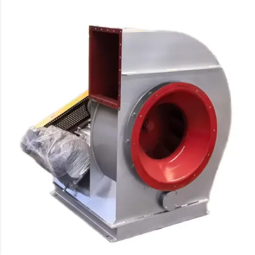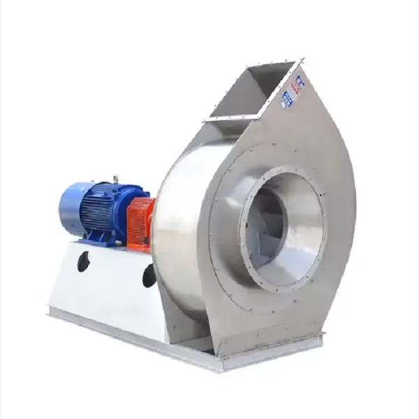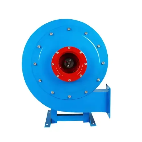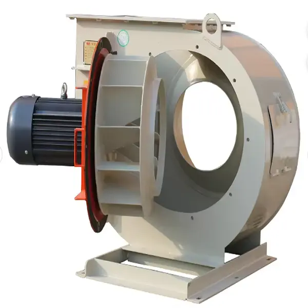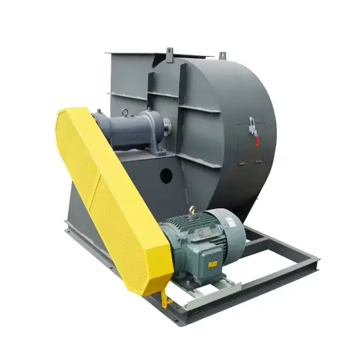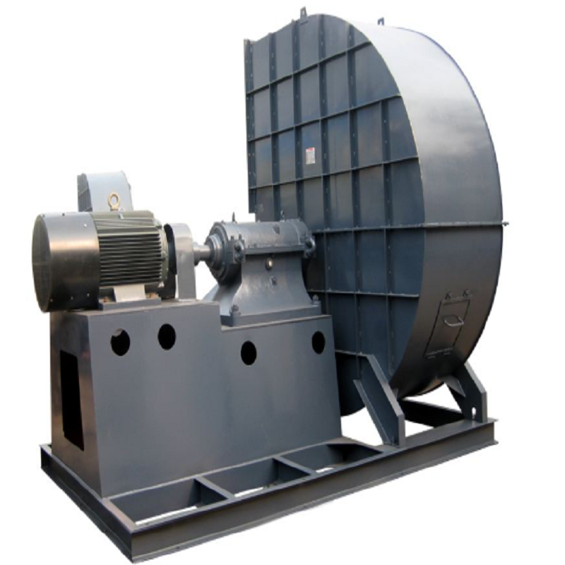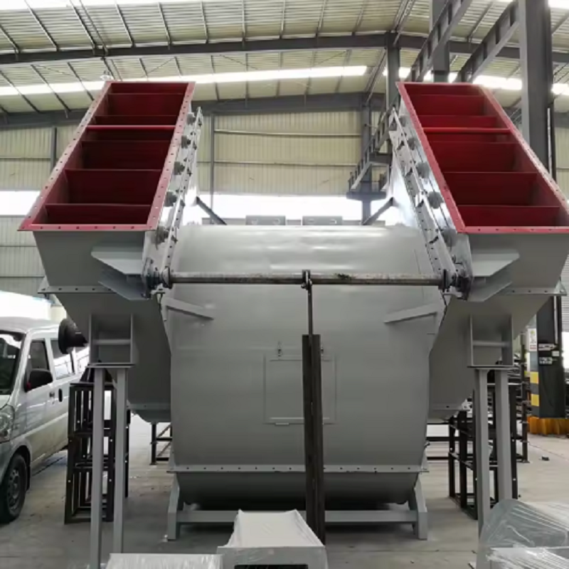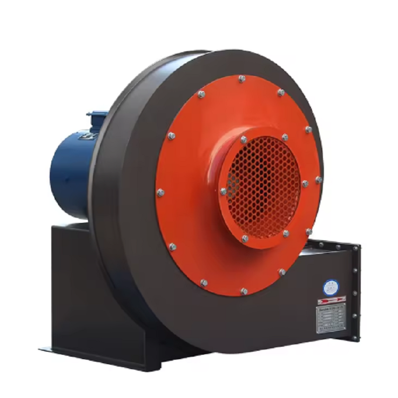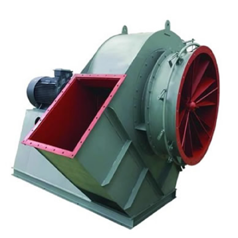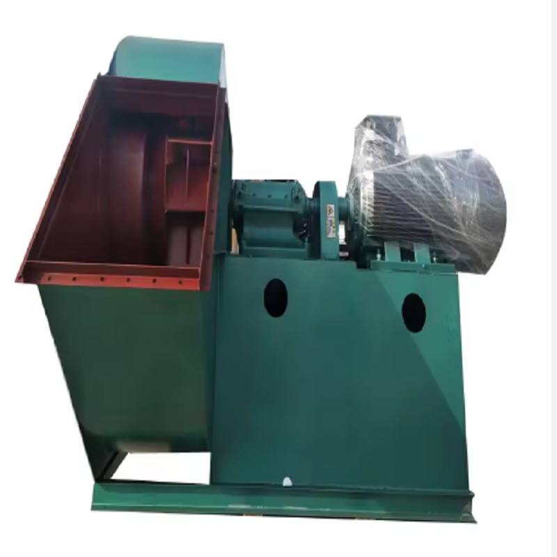
As industrial plants place greater emphasis on process stability, energy consumption, and workplace air quality, the use of the Centrifugal Fan is expanding across furnace exhaust, boiler systems, dust collection, and other demanding ventilation applications. Unlike simple ventilation equipment, an industrial Centrifugal Fan must be selected according to the actual operating point, including airflow, static pressure, gas temperature, dust concentration, and system resistance. In many projects, fan performance is determined less by the nameplate airflow than by whether the fan can maintain stable operation after ducts, filters, dampers, cyclones, and other resistance components are connected.
Furnace exhaust is one of the more demanding applications for a Centrifugal Fan because the gas temperature can change significantly during production. For a furnace operating at an exhaust gas temperature of 250–350°C, the fan selection should not be based only on the normal air volume. Gas density decreases as temperature rises, which changes the pressure characteristics and motor operating conditions.
A practical approach is to first determine the required flow at the actual operating temperature, then calculate the total system resistance. For example, assume a furnace requires 45,000 m³/h of exhaust flow with a total system resistance of 2,200 Pa. If the system contains a long duct run, a high-temperature filter, several elbows, and a damper, selecting a fan only according to the 45,000 m³/h figure can result in insufficient pressure. In this case, a Centrifugal Fan with an appropriate pressure margin and temperature-rated bearing arrangement is more suitable than simply selecting a larger fan.
In one furnace ventilation application, the original fan was selected at approximately 40,000 m³/h, but actual production conditions required closer to 47,000 m³/h. Operators found that the furnace pressure became unstable whenever the production rate increased. After checking the system, the main issue was not the motor size but the additional resistance created by a partially blocked filter and undersized duct sections.
The solution was to clean and replace the filter, correct the duct restriction, and select a Centrifugal Fan based on the revised system curve. After commissioning, the furnace maintained a more stable negative pressure and the fan operated closer to its efficient operating point. This illustrates why system resistance should be verified before increasing fan size.
Boiler applications often require continuous operation, making reliability as important as rated airflow. A boiler-induced draft Centrifugal Fan must provide stable pressure against changing flue gas conditions, especially when the system includes economizers, dust collectors, scrubbers, or other gas-treatment equipment.
For a boiler system, engineers normally determine the required flow from fuel consumption and combustion requirements, then calculate the resistance of the complete flue gas path. A common mistake is to increase fan capacity when draft is insufficient without checking whether the actual problem comes from excessive resistance. If a dust collector has accumulated ash, for example, the pressure drop may increase substantially while the Centrifugal Fan continues to run at the same speed.
Variable frequency drive control can also be useful when boiler load changes throughout the day. Instead of operating the Centrifugal Fan continuously at full speed and throttling with a damper, a VFD can adjust fan speed according to actual draft demand. Since fan power consumption is strongly affected by rotational speed, reducing speed under partial load can produce meaningful energy savings when the system is properly designed.
Industrial dust collection is another major application area for the Centrifugal Fan. Compared with clean-air ventilation, dust-laden gas can cause faster impeller wear, imbalance, and efficiency loss. This is especially noticeable in cement plants, foundries, steel processing lines, woodworking facilities, and mineral handling systems.
When selecting a Centrifugal Fan for dusty air, the dust characteristics should be evaluated first. Particle size, concentration, abrasiveness, moisture content, and temperature all affect the fan design. Abrasive particles may require reinforced impeller components or wear-resistant construction. Where dust can accumulate on the blades, the impeller geometry and cleaning access should also be considered.
Consider a grinding workshop that requires approximately 30,000 m³/h of extraction air. After several months of operation, operators notice increased vibration and reduced suction at the collection points. The first assumption is often bearing wear, but inspection reveals significant dust buildup on the impeller.
Even a relatively thin and uneven layer of deposits can alter impeller balance. Once imbalance develops, vibration rises and bearing life can decrease. After cleaning and dynamic balancing, the Centrifugal Fan can recover much of its original performance. This is why regular impeller inspection should be included in the maintenance schedule rather than waiting for abnormal vibration to occur.
A reliable Centrifugal Fan selection begins with four basic parameters: required airflow, total pressure, operating temperature, and gas composition. These should be supported by information about dust load, corrosiveness, installation altitude, operating hours, and available power supply.
For example, a process requiring 60,000 m³/h at 2,500 Pa is fundamentally different from a system requiring the same airflow at 900 Pa. The two applications may use different impeller geometries, rotational speeds, motor powers, and transmission arrangements. Selecting equipment based only on airflow can lead to excessive power consumption or an inability to reach the required pressure.
It is also important to distinguish static pressure from total pressure during technical communication. A supplier receiving only an airflow value cannot accurately determine the correct Centrifugal Fan. A complete specification should normally include flow, pressure, gas temperature, gas density or composition, dust concentration, installation conditions, motor voltage, frequency, and duty cycle.
Even a correctly selected Centrifugal Fan can underperform because of poor installation. Inlet turbulence, insufficient straight duct length, sudden duct contractions, poorly positioned elbows, and improper damper settings can shift the actual operating point away from the design condition.
A practical commissioning procedure should include checking the fan rotation direction, motor current, bearing temperature, vibration velocity, inlet and outlet pressure, and actual airflow. If measured airflow is lower than expected, operators should not immediately increase fan speed. The first step should be to identify whether the system resistance is higher than predicted.
Alignment is another critical point for belt-driven equipment. Excessive belt tension increases bearing loading, while insufficient tension can cause slipping and unstable speed. For directly coupled fans, shaft alignment and coupling condition should be inspected carefully. These details have a direct effect on the service life of the Centrifugal Fan.
Routine maintenance for a Centrifugal Fan should include vibration checks, bearing temperature monitoring, lubrication inspection, impeller cleaning, belt condition checks, and electrical connection inspection. More importantly, maintenance teams should record these values over time.
A vibration value that remains stable is generally less concerning than a value that gradually increases over several weeks. The same principle applies to bearing temperature and motor current. Trend data can reveal developing problems before they become emergency shutdowns.
For dusty industrial systems, inspection intervals should be adjusted according to actual operating conditions. A fan handling heavy abrasive dust may require much more frequent impeller inspection than a fan handling clean air. In high-temperature applications, bearing arrangements, lubrication methods, shaft cooling, and expansion considerations should also be reviewed as part of the maintenance plan.
Improving the efficiency of a Centrifugal Fan does not always require replacing the fan. In many existing plants, the larger opportunity is to correct oversized equipment, excessive throttling, duct restrictions, or poor operating practices.
For example, if a fan is designed for 70,000 m³/h but the process normally requires only 52,000 m³/h, continuously operating at full speed and controlling flow through a damper wastes energy. A properly configured VFD can reduce speed to match the actual process requirement. Before implementing this change, however, the fan curve, motor characteristics, minimum operating speed, and system stability should all be checked.
The best results typically come from treating the fan and ductwork as one system. A highly efficient Centrifugal Fan connected to poorly designed ducts can still consume excessive power, while a well-balanced system can achieve the required airflow with a smaller and more stable operating load.
The growing use of the Centrifugal Fan in furnace exhaust, boiler systems, and industrial dust collection reflects the increasing technical demands placed on industrial ventilation equipment. These applications require more than selecting a fan by airflow alone. Temperature, pressure, dust load, gas properties, duct resistance, maintenance conditions, and operating schedules all influence the final result.
From furnace negative-pressure control to boiler draft management and abrasive dust extraction, a properly engineered Centrifugal Fan can provide reliable airflow while reducing unnecessary energy consumption and maintenance risk. In practical projects, the most effective approach is to begin with the complete system requirements, verify the operating point, and then match the fan design to the actual process rather than forcing the process to fit a standard fan specification.