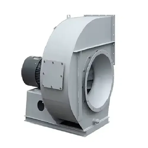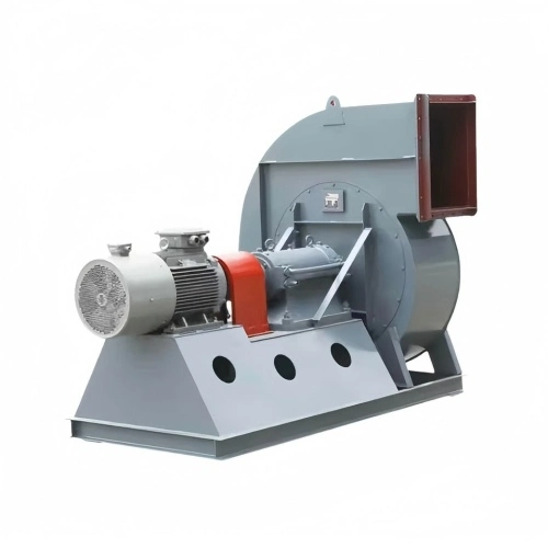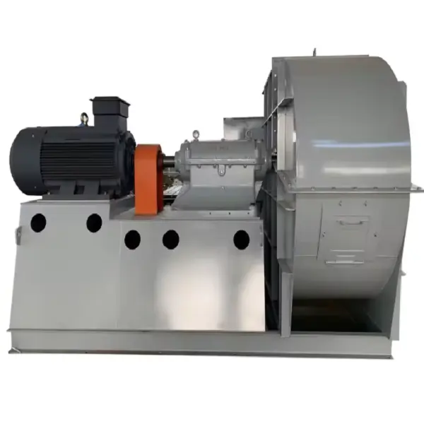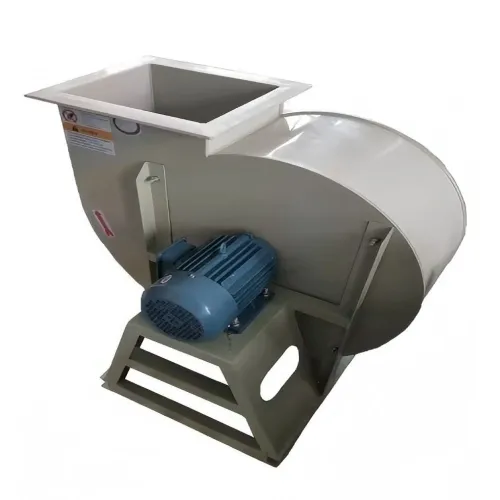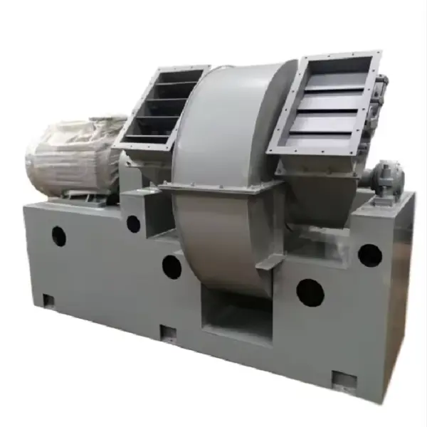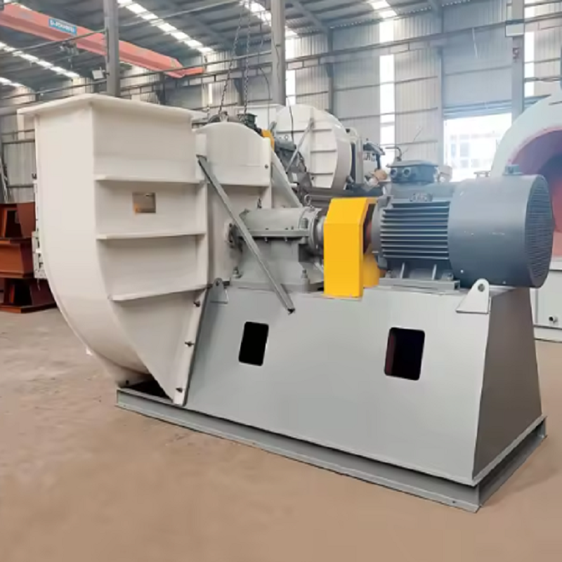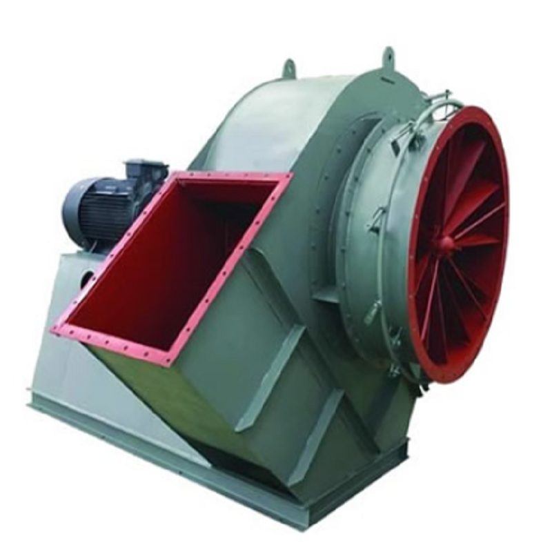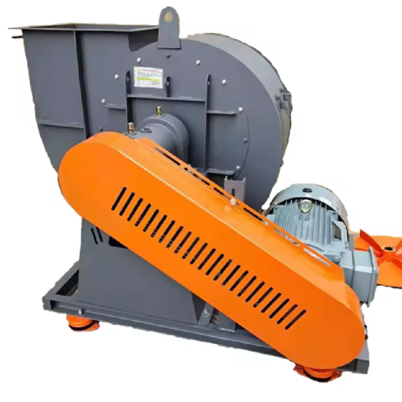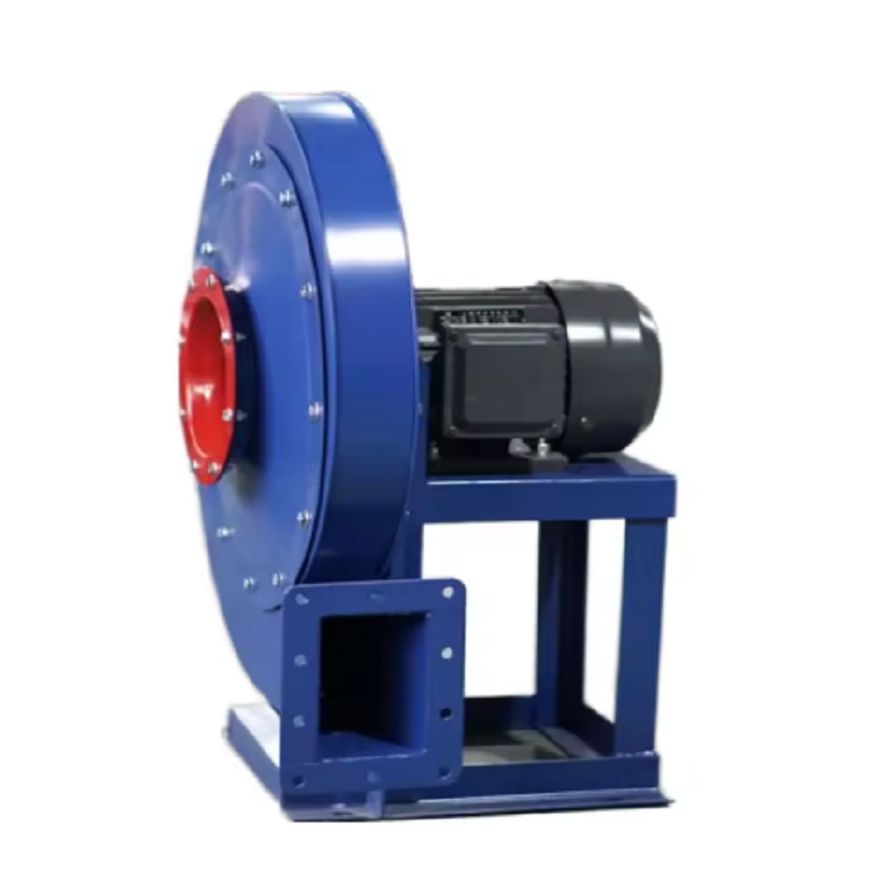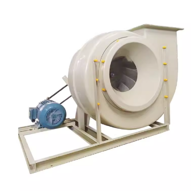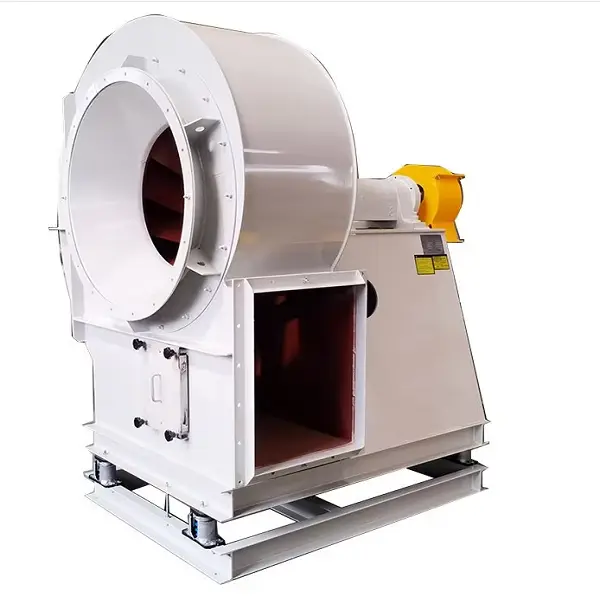
Power plants are under continuous pressure to reduce auxiliary power consumption while maintaining stable boiler operation. Among the major auxiliary systems, the flue gas system can consume a significant amount of electricity because induced draft fans must overcome the resistance of air preheaters, dust collectors, desulfurization equipment, ducts, dampers, and other equipment. High-Efficiency Power Plant Induced Draft Fans can help reduce this electrical demand by combining efficient impeller design, accurate operating-point selection, and appropriate airflow control.
An induced draft fan operates after the boiler and pollution-control equipment and is responsible for moving flue gas through the downstream system while maintaining the required furnace draft. Unlike a ventilation fan operating with relatively clean air, a power plant ID fan may handle hot gas containing dust, moisture, and corrosive components. These conditions can change the actual operating point and increase fan power consumption.
High-Efficiency Power Plant Induced Draft Fans should therefore be selected according to the complete operating condition rather than only the maximum airflow. Engineers should determine the required flow rate, system pressure, gas temperature, gas density, dust concentration, operating altitude, and expected load range before selecting the fan.
For example, suppose a boiler requires 180,000 m³/h of flue gas at a design pressure of 3,200 Pa. Selecting a fan simply because its rated capacity is 180,000 m³/h is not sufficient. If the actual system resistance is lower than expected, the fan may operate at excessive airflow, increasing motor power consumption. If the resistance is higher, the fan may fail to maintain the required boiler draft.
Fan speed is one of the most important factors affecting induced draft fan power. According to the fan affinity laws, airflow changes approximately in proportion to rotational speed, pressure changes approximately with the square of speed, and power changes approximately with the cube of speed. The U.S. Department of Energy's industrial fan guidance specifically highlights the strong relationship between fan speed and power consumption.
The basic relationship can be expressed as:
Q₂ / Q₁ = N₂ / N₁
P₂ / P₁ = (N₂ / N₁)³
where Q is airflow, N is rotational speed, and P is fan power.
For example, if an ID fan operates at 1,000 rpm and consumes 500 kW, reducing the speed to 900 rpm under an appropriate system condition gives a theoretical power ratio of:
(900 / 1,000)³ = 0.729
The theoretical fan power would therefore be about 365 kW before considering motor, drive, system, and operating-condition effects. This illustrates why High-Efficiency Power Plant Induced Draft Fans are often combined with variable-speed control instead of relying entirely on throttling.
Traditional induced draft fan systems may use inlet or outlet dampers to control flue gas flow. A damper reduces flow by increasing system resistance, which means the fan can continue consuming substantial power while part of the available pressure is simply dissipated across the control device.
A variable frequency drive provides another approach. Instead of producing excessive pressure and then wasting that pressure through a damper, the fan speed can be adjusted closer to the actual boiler demand.
This is particularly useful when the boiler operates across a wide load range. During low-load operation, the fan does not necessarily need to run at its full design speed.
A U.S. Department of Energy case study involving waste-to-energy boilers replaced damper-based control of 500-hp induced draft fans with VFD control. The modified system allowed fan speed to track the boiler draft requirement while the inlet dampers could remain fully open, eliminating the pressure loss associated with throttling.
For High-Efficiency Power Plant Induced Draft Fans, the practical objective is not simply installing a VFD. The control system should maintain the required furnace pressure while avoiding unnecessary fan speed, excessive airflow, and unstable operation.
A common mistake during fan selection is choosing a fan with a large safety margin in both airflow and pressure. A large margin may appear safe during the design stage, but an oversized fan can operate far away from its best efficiency point during normal plant operation.
Consider a practical example:
Required airflow: 200,000 m³/h
Required pressure: 2,800 Pa
Normal boiler load: 70–90%
Flue gas temperature: 140°C
Dust-containing flue gas
Variable boiler load
If the selected fan is capable of 240,000 m³/h at a substantially higher pressure, operators may need to use dampers to restrict the airflow during normal operation. This creates unnecessary pressure loss.
A better approach is to examine the complete fan curve and system resistance curve. The selected operating point should fall within the efficient region of the fan curve while providing enough margin for realistic changes in system resistance.
This is one of the most important design principles for High-Efficiency Power Plant Induced Draft Fans: efficiency must be evaluated at the actual operating point, not only at the fan's nominal maximum capacity.
The impeller is another major factor affecting fan efficiency. Different impeller blade profiles have different efficiency, stability, noise, and erosion characteristics. DOE's boiler energy-efficiency handbook notes that several ID/FD fan configurations are commonly used in power plants, including backward-curved or airfoil designs, straight-blade designs, and radial-tip designs. It also notes that airfoil designs can provide high efficiency and stable operation, while some other configurations are more suitable for erosive service.
However, the most efficient blade profile on paper is not automatically the best choice for every power plant.
For a high-dust application, engineers must also consider:
Particle concentration
Particle size
Gas velocity
Impeller tip speed
Blade erosion
Material hardness
Expected operating hours
Cleaning requirements
For example, an impeller handling abrasive ash may gradually lose its original aerodynamic profile. Even if the fan was initially tested at high efficiency, erosion can increase slip and aerodynamic losses over time.
Therefore, High-Efficiency Power Plant Induced Draft Fans should be evaluated over their expected service life rather than only during factory testing.
When an existing ID fan cannot achieve the required airflow, increasing fan speed is not always the correct solution.
First measure the pressure loss across the major components:
Air preheater
Electrostatic precipitator or baghouse
Desulfurization system
SCR system
Expansion joints
Dampers
Silencers
Duct elbows
Long duct sections
For example, assume the original design pressure loss of a flue gas system was 2,500 Pa, but actual operation shows 3,100 Pa. Increasing fan speed to compensate may increase motor power considerably.
A better engineering approach is to identify where the additional 600 Pa is being generated. A blocked filter, excessive ash accumulation, partially closed damper, fouled heat exchanger, or poorly designed duct transition can all increase resistance.
Reducing unnecessary system resistance can allow the existing fan to deliver the required airflow at a lower speed. This can be more energy-efficient than simply installing a larger motor or higher-speed impeller.
Consider a boiler where the design airflow is 200,000 m³/h at 2,500 Pa. During commissioning, measurements show that the fan is delivering approximately 225,000 m³/h while the boiler only requires 200,000 m³/h.
The first step should be to confirm the measurement accuracy. Engineers should check airflow measurement devices, pressure transmitters, fan speed, damper position, and boiler operating conditions.
If the measurement is confirmed, the next step is to determine whether the excess airflow is caused by excessive fan speed or a change in system resistance.
Assume the fan speed is 1,000 rpm and the airflow is approximately proportional to speed. A preliminary speed estimate would be:
N₂ = 1,000 × (200,000 / 225,000)
N₂ ≈ 889 rpm
This is only a starting estimate. The final speed must be determined from the actual fan curve and system curve, and the boiler draft must remain within the required operating range.
This type of optimization is where High-Efficiency Power Plant Induced Draft Fans can provide practical energy benefits: instead of continuously throttling excessive airflow, the fan can operate closer to the required duty point.
Energy efficiency should never be evaluated separately from mechanical reliability.
After changing fan speed or control parameters, technicians should monitor:
Motor current
Motor power
Fan speed
Airflow
Fan pressure
Furnace pressure
Bearing temperature
Fan vibration
Damper position
Flue gas temperature
A reduction in motor power is not automatically a successful optimization if the fan becomes unstable or the boiler draft fluctuates.
For example, if reducing fan speed from 1,000 to 880 rpm lowers electrical consumption but causes furnace pressure to fluctuate outside the required control range, the optimization should be reconsidered.
The practical target for High-Efficiency Power Plant Induced Draft Fans is stable operation at the lowest reasonable energy consumption, not simply the lowest possible fan speed.
Fan efficiency can gradually deteriorate because of operating conditions. Dust accumulation on the impeller is one common problem in flue gas applications.
An uneven layer of ash can create two problems simultaneously. First, it changes the aerodynamic surface of the blades and may reduce performance. Second, uneven deposits can create rotor imbalance and increase vibration.
During planned maintenance, technicians should inspect:
Impeller blade surfaces
Blade thickness
Welded joints
Shaft condition
Bearing condition
Coupling alignment
Rotor balance
Casing clearance
Damper operation
VFD and motor parameters
If vibration increases after several months of operation, the maintenance team should not immediately assume that the bearing is defective. Impeller fouling, erosion, misalignment, loose foundation bolts, and coupling problems should also be investigated.
Suppose an existing ID fan consumes an average of 600 kW and operates 7,000 hours per year.
Annual electricity consumption is:
600 × 7,000 = 4,200,000 kWh
If an optimization project reduces average fan power by 12%, the estimated annual saving is:
4,200,000 × 12% = 504,000 kWh/year
The actual financial saving depends on the plant's electricity cost and operating schedule.
This calculation should be performed using measured operating data rather than relying only on theoretical fan curves. For a retrofit project, technicians should record power, airflow, pressure, fan speed, and boiler load before and after optimization.
Temperature has a direct impact on gas density and therefore on fan performance. The same volumetric airflow at different temperatures does not represent the same gas mass flow.
For power plant ID fans, engineers should specify:
Normal gas temperature
Maximum gas temperature
Minimum gas temperature
Gas composition
Gas density
Moisture content
Dust concentration
Corrosive components
If the fan is selected using incorrect gas density, the calculated pressure and shaft power can be misleading.
High-Efficiency Power Plant Induced Draft Fans therefore require performance calculations based on the actual flue gas condition rather than simply using standard-air performance data.
A fan's rated efficiency does not guarantee that the complete fan system will operate efficiently after installation.
Actual plant performance depends on the interaction between:
Fan curve + system curve + control method + gas condition + boiler load
The U.S. Department of Energy identifies improving FD/ID fan efficiency and using variable-frequency drives as potential ways to reduce auxiliary energy use in flue gas systems.
For this reason, commissioning should include performance measurements at several operating loads rather than checking only one point.
Reducing ID fan energy consumption is not simply a matter of installing a larger or more efficient fan. The complete system must be considered, including fan selection, impeller design, operating point, system resistance, control method, flue gas conditions, maintenance, and boiler load.
High-Efficiency Power Plant Induced Draft Fans can provide meaningful energy-saving potential when they are correctly matched to the actual flue gas system and controlled according to real boiler demand. In many applications, reducing unnecessary pressure generation, minimizing damper throttling, using variable-speed control, and maintaining the impeller can produce better results than increasing fan capacity.
For a new power plant project, the most useful starting point is a complete duty specification: airflow, pressure, temperature, gas composition, dust concentration, altitude, operating range, fan arrangement, motor power, and control method. For an existing plant, measured operating data should be collected first. Comparing actual airflow, pressure, speed, power consumption, vibration, and boiler load can then show where the largest efficiency improvements are available.