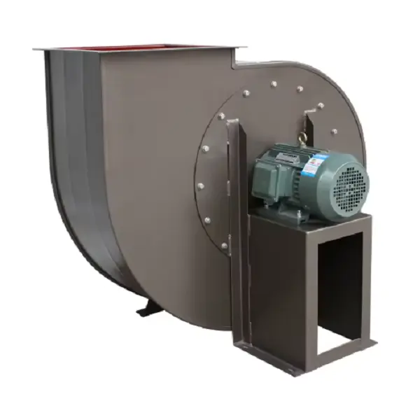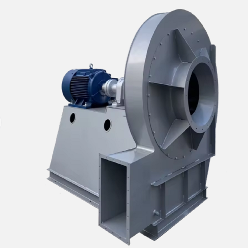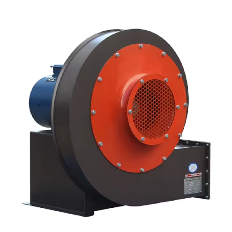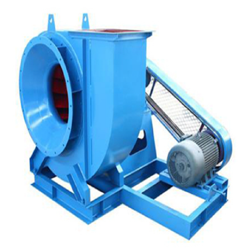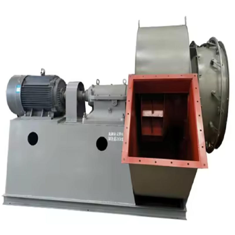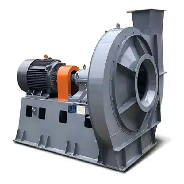
An Industrial Centrifugal Fan can consume a significant amount of electricity when it operates continuously in a manufacturing plant. In many older ventilation and exhaust systems, the fan itself is not necessarily inefficient; the larger problem is that the Industrial Centrifugal Fan is often running at a higher speed, pressure, or airflow than the process actually requires. Before replacing the equipment, plant engineers should measure the existing operating condition and determine where the excess energy is being used.
The first step in improving an Industrial Centrifugal Fan system is to establish a reliable operating baseline. Record airflow, static pressure, fan speed, motor current, motor power, bearing temperature, vibration, and operating hours. Damper position should also be recorded because a fan operating at 100% speed with a heavily closed damper is often a clear indication of a mismatch between fan capacity and system demand.
For example, a factory may have an Industrial Centrifugal Fan originally selected for 30,000 m³/h at 2,000 Pa, while the current process only requires approximately 22,000 m³/h. If the fan continues operating at full speed and the airflow is controlled by a damper, the motor is still consuming much of its rated power. Measuring the actual system conditions provides the information needed before making any modification.
A common energy-saving opportunity for an Industrial Centrifugal Fan is hidden behind the inlet or outlet damper. A damper reduces airflow by increasing system resistance, but it does not directly reduce the rotational speed of the fan. The motor therefore continues driving the impeller at the same speed while part of the available pressure is dissipated across the damper.
During an inspection, technicians should record the damper opening and compare it with the required process airflow. If an Industrial Centrifugal Fan normally operates with the damper only 50–60% open, engineers should investigate whether the fan speed can be reduced instead. In suitable applications, installing a variable frequency drive (VFD) can provide much better control than continuous mechanical throttling.
Fan speed reduction can produce a substantial reduction in power consumption because centrifugal fan power changes rapidly with speed. Under similar system conditions, fan affinity laws indicate that airflow is approximately proportional to speed, pressure varies approximately with the square of speed, and power varies approximately with the cube of speed.
For an Industrial Centrifugal Fan running at 50 Hz, reducing speed to 45 Hz represents a speed ratio of 0.90. The theoretical power ratio is approximately:
P₂ / P₁ ≈ (45 / 50)³ = 0.729
This means the theoretical fan power can fall to roughly 73% of the original value, although actual savings depend on the system curve, motor efficiency, transmission losses, and operating point. Engineers should therefore measure the system after adjustment rather than assuming the theoretical value will always be achieved.
Impeller contamination is another overlooked source of energy loss in an Industrial Centrifugal Fan. Dust, oil mist, fibers, or process particles can accumulate on blades and alter the aerodynamic profile. Heavy deposits can also create imbalance, increasing vibration and bearing loads.
Before modifying an Industrial Centrifugal Fan, inspect the impeller through the access door or after proper isolation and lockout. Check for dust buildup, erosion, corrosion, damaged blades, and deposits concentrated on one side of the wheel. In one practical example, a dust extraction fan showed increasing vibration and reduced airflow after several months of operation. Cleaning the impeller restored airflow and reduced vibration without changing the motor or fan casing.
An Industrial Centrifugal Fan does not operate independently from the duct system. When filters become blocked, ducts accumulate material, elbows are poorly arranged, or dampers are partially closed, system resistance increases and the fan must generate more pressure.
A useful field inspection should include filters, duct transitions, elbows, silencers, dampers, heat exchangers, scrubbers, and discharge openings. If a filter has a significantly higher pressure drop than its clean condition, replacing or cleaning the filter may save more energy than modifying the Industrial Centrifugal Fan itself. This is especially important in dust collection systems where filter resistance gradually increases during normal operation.
Every Industrial Centrifugal Fan has a performance curve showing the relationship between airflow, pressure, speed, and efficiency. Actual operating conditions should be compared with the manufacturer's fan curve whenever reliable operating data are available.
Suppose an Industrial Centrifugal Fan was designed for 25,000 m³/h at 1,800 Pa but is currently producing 19,000 m³/h at 2,300 Pa. The difference may indicate increased system resistance, incorrect damper settings, a change in process conditions, or an operating point far from the fan's best efficiency region. Simply installing a larger motor would not solve the underlying problem. The system should first be analyzed to determine why the operating point has shifted.
Consider an existing Industrial Centrifugal Fan used for dust extraction in a metal-processing workshop. The fan was driven by a 30 kW motor and operated approximately 6,000 hours per year. Measurements showed that the process required around 18,000 m³/h, while the fan was delivering approximately 22,000 m³/h. The outlet damper was partially closed to control the excess airflow.
The plant installed a VFD and adjusted the Industrial Centrifugal Fan speed to match the required airflow. After commissioning, airflow was maintained near the required process value while motor power decreased substantially. The actual saving should be calculated from measured kW before and after the modification. For example, if average input power falls from 24 kW to 16 kW, annual electricity consumption is reduced by approximately:
(24 − 16) × 6,000 = 48,000 kWh/year
This example also demonstrates why measuring actual motor power is more useful than estimating savings only from motor nameplate capacity.
Energy optimization does not mean simply slowing an Industrial Centrifugal Fan as much as possible. Insufficient airflow can cause poor fume capture, excessive dust concentration, furnace pressure instability, overheating, or failure to meet environmental requirements.
When adjusting an Industrial Centrifugal Fan, engineers should establish minimum acceptable airflow and pressure based on the actual process. For local exhaust ventilation, for example, capture performance must remain adequate at the hood. For boiler or furnace applications, furnace pressure and combustion requirements may be more important than simply reducing airflow.
Mechanical condition also affects the efficiency of an Industrial Centrifugal Fan system. Worn bearings, poor lubrication, shaft misalignment, belt slip, incorrect belt tension, and coupling problems can increase mechanical losses and vibration.
For belt-driven Industrial Centrifugal Fan systems, technicians should check belt condition and tension and verify pulley alignment. For direct-drive configurations, shaft alignment, bearing condition, and motor efficiency should be checked. A motor drawing abnormal current should not automatically be blamed on the motor; excessive fan load, system resistance, mechanical friction, or operating conditions may be the real cause.
In some cases, an existing Industrial Centrifugal Fan is fundamentally oversized or has an impeller design that does not match the current process. If the fan operates continuously far from its efficient operating region, repeated throttling and speed adjustments may only provide a partial solution.
A replacement Industrial Centrifugal Fan can be considered when the existing fan has severe wear, poor aerodynamic efficiency, unsuitable materials, excessive pressure capability, or a capacity significantly higher than the actual requirement. The replacement should be selected using measured airflow and system pressure rather than simply matching the existing motor power.
Before modifying an Industrial Centrifugal Fan, plant engineers can use the following sequence:
Measure actual airflow and static pressure.
Record motor input power and current.
Record fan speed and damper position.
Inspect the impeller for dust, corrosion, and wear.
Check filter and duct pressure losses.
Compare actual operating conditions with the fan performance curve.
Determine whether the fan is oversized.
Evaluate VFD speed control where applicable.
Check motor, bearings, belts, couplings, and shaft alignment.
Re-measure airflow, pressure, and power after modification.
The most effective approach is to treat the Industrial Centrifugal Fan as part of the entire air-handling system rather than as an isolated machine. In many plants, significant savings can be achieved through better operating-point control, reduced system resistance, regular impeller cleaning, and appropriate speed regulation without immediately replacing the fan.
For plants with continuously operating ventilation or exhaust equipment, even a small reduction in power can accumulate into substantial annual savings. A properly optimized Industrial Centrifugal Fan should provide only the airflow and pressure required by the process, at the lowest practical energy consumption, while maintaining safe and stable operation.